Multipath non-overlapped switching circuit

A switching circuit, non-overlapping technology, applied in the direction of logic circuits with logic functions, reliability improvement and modification, etc., can solve the problems of limited application scenarios and unsatisfactory effects.

Active Publication Date: 2017-02-22
CHIPSEA TECH SHENZHEN CO LTD
View PDF4 Cites 2 Cited by
  • Summary
  • Abstract
  • Description
  • Claims
  • Application Information

AI Technical Summary

Problems solved by technology

However, the control signal of this patent application can only turn on the switch tubes in a fixed order, and the application scenarios are limited.
And the control signal turns on the power switch tube after passing through the switch drive circuit. Since the size of the power switch tube is usually large, there will be a certain delay for the control signal to turn on the power switch tube. The delay overlaps, so the effect is not ideal

Method used


Image

  • Multipath non-overlapped switching circuit
  • Multipath non-overlapped switching circuit
  • Multipath non-overlapped switching circuit

Examples


Embodiment Construction

[0019] In order to make the object, technical solution and advantages of the present invention clearer, the present invention will be further described in detail below in conjunction with the accompanying drawings and embodiments. It should be understood that the specific embodiments described here are only used to explain the present invention, not to limit the present invention.

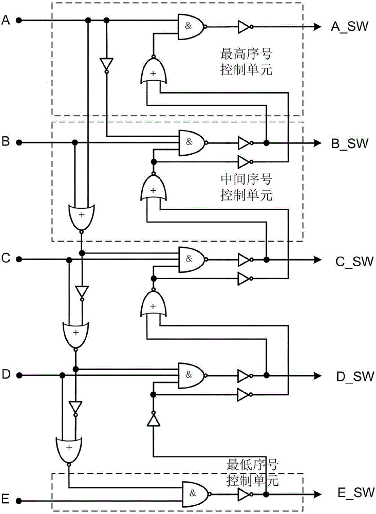
[0020] image 3 Shown is the embodiment 1 of the multi-channel non-overlapping switch circuit implemented in the present invention, and the embodiment 1 takes a five-way switch control circuit as an example. Multiple non-overlapping switch circuits, which include one highest signal control unit, one lowest signal control unit and three intermediate signal control units (usually the number of intermediate signal control units depends on the number of switches, except for the highest signal control unit and the lowest Except the signal control unit, the rest are intermediate signal control units). ...


PUM


Abstract

The invention discloses a multipath non-overlapped switching circuit, and the circuit comprises a plurality of switches and corresponding switching control signals. Each switching control signal is used for logic control through a logic gate and a phase inverter. Moreover, adjacent multipath switches are connected through the phase inverter and the logic gate, so as to achieve the integrated control of the switching signals, and achieve a purpose that at most one switch is turned on at the same moment. The switching circuit avoids node voltage oscillation caused by the simultaneous switching-on of two switches, and prevents an overlarge current from flowing through the switch. Moreover, the switching circuit is easier to achieve the extension of any non-overlapped switches.

Description

technical field [0001] The invention belongs to the technical field of integrated circuits, in particular to a switch circuit of an integrated circuit. Background technique [0002] A multi-way switch is often used in the circuit. The function of the circuit is to connect different signals to a certain node according to the control signal. The principle of multi-way switch is as figure 1 As shown, for example, when SW2 turns on the corresponding switch and the other switches are turned off, the node NIN is connected to N2. [0003] In some high-speed application scenarios, fast switching switches are required. Due to the delay of the signal on the line, or due to improper consideration by the designer, at a certain moment, two switches may be turned on at the same time. For example figure 1 As shown, SW3 and SW4 turn on the corresponding switch when they are at a high level. In a short time tn1, SW3 and SW4 are turned on at the same time, and N3 and N4 are connected to N...

Claims


Application Information

Patent Timeline
Patent Type & Authority Applications(China)
IPC IPC(8): H03K19/003H03K19/20
CPCH03K19/003H03K19/20
Inventor 李弦
Owner CHIPSEA TECH SHENZHEN CO LTD
Why Eureka
Try Eureka