
Multi-phase and high-power generation-conversion integrated system and control method thereof

A control method and high-power technology, which can be used in the conversion of AC power input to AC power output, climate change adaptation, and output power conversion devices, etc. Complex problems, etc., to achieve the effect of shortened installation and commissioning cycle, considerable application prospects, and high degree of structural modularity

Active Publication Date: 2017-02-22
湖南中聚福能源科技有限公司
View PDF4 Cites 6 Cited by
  • Summary
  • Abstract
  • Description
  • Claims
  • Application Information

AI Technical Summary

Problems solved by technology

However, this topology also has disadvantages such as complex system structure, difficult control, large number of full-control devices, high cost, and the need to use large-capacity filters on the motor side or grid side.
In addition, this topology generally needs to be boosted by a step-up transformer before it can be connected to the grid, thus resulting in a complex system structure and a substantial increase in device size and cost
Due to the limitation of converter capacity and other reasons, its application in the grid connection of larger power plants is not the optimal solution

Method used


Image

  • Multi-phase and high-power generation-conversion integrated system and control method thereof
  • Multi-phase and high-power generation-conversion integrated system and control method thereof
  • Multi-phase and high-power generation-conversion integrated system and control method thereof

Examples


Embodiment Construction

[0043] The present invention will be further described below in conjunction with the accompanying drawings.

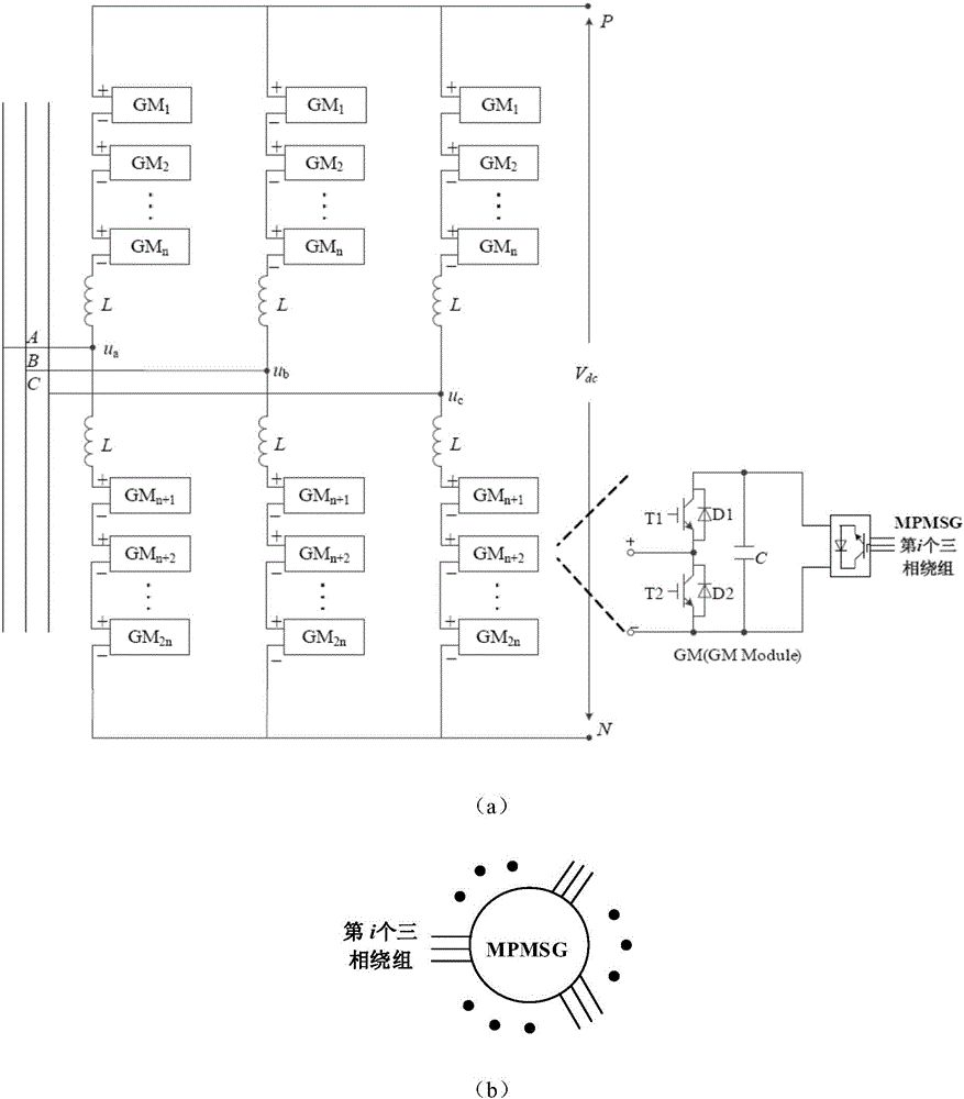
[0044] figure 1 It is a topology structure and sub-module diagram of a multi-phase high-power power generation-conversion integrated system of the present invention. The modular multi-level inverter adopts a three-phase structure of A, B, and C, and each phase consists of an upper bridge arm and a lower bridge arm. The bridge arm is composed of series connection, the upper bridge arm is composed of n sub-modules and 1 filter inductor in series, the lower bridge arm is composed of 1 filter inductor and n sub-modules in series, and the connection point of the two filter inductors constitutes the corresponding phase bridge arm The output end of the output end is connected to the public power grid; the upper ends of the three-phase upper bridge arms of A, B, and C are connected to each other, the lower ends of the three-phase lower bridge arms of A, B, and C are connected ...


PUM


Abstract

The invention discloses a multi-phase and high-power generation-conversion integrated system and a control method thereof. The multi-phase and high-power generation-conversion integrated system comprises a modular multilevel inverter and a multi-phase permanent magnet generator, wherein a three-phase structure is adopted by the modular multilevel inverter; each phase is formed by connecting an upper bridge arm and a lower bridge arm in series; each bridge arm is formed by connecting n sub-modules and a filter inductor in series; connection points of the filter inductors of the upper bridge arms and the lower bridge arms form output ends of the bridge arms of the corresponding phases to be connected to a public power network; each sub-module comprises a three-phase PWM rectifier, a capacitor and two series-connected IGBT tubes; 6n three-phase windings of the multi-phase permanent magnet generator are connected to AC ends of 6n three-phase PWM rectifiers of the modular multilevel inverter in a manner of one-to-one correspondence; and a DC output end of each three-phase PWM rectifier is connected with the corresponding capacitor in parallel and also connected with two ends of two corresponding series-connected IGBT tubes in parallel. The multi-phase and high-power generation-conversion integrated system has a modular structure design and a good control characteristic, and flexible connection between a power generation system and the power network is easy to implement.

Description

technical field [0001] The patent of the invention belongs to the technical field of power generation, and in particular relates to a multi-phase high-power power generation-conversion integrated system and a control method thereof. Background technique [0002] From the perspective of global energy supply, the gradual depletion of fossil energy is a fact. In order to maintain the sustainable development of the global economy, how to ensure sufficient energy supply, how to develop various forms of energy, and how to directly convert these energies into electrical energy that can be directly used by human beings is an important issue facing all mankind. As the core equipment for converting various forms of clean and renewable energy such as thermal energy, wind energy, and tidal energy into electrical energy, generators play a key role in the process of realizing electromechanical energy conversion. The application fields of generators are not limited to traditional thermal ...

Claims


Application Information

Patent Timeline
Patent Type & Authority Applications(China)
IPC IPC(8): H02J3/38H02M5/458
CPCH02J3/382H02M5/4585Y02A30/60
Inventor 黄守道饶志蒙荣飞高剑李孟秋罗德荣
Owner 湖南中聚福能源科技有限公司
Learn More