
A method for a helicopter to deploy a guide rope

A guide rope and helicopter technology, which is applied in the direction of thin material handling, overhead line/cable equipment, and conveying filamentous materials, etc., can solve the problems of multiple winding layers and long time consumption, so as to reduce work, improve safety and The effect of construction efficiency

Active Publication Date: 2018-03-16
SGCC GENERAL AVIATION +1
View PDF7 Cites 0 Cited by
  • Summary
  • Abstract
  • Description
  • Claims
  • Application Information

AI Technical Summary

Problems solved by technology

[0028] The laying type is suitable for laying out fiber ropes such as the initial guide, and there are still many layers of subsequent winding; the pulley on the tower needs a lot of manual assistance to enter the groove, and it takes a long time

Method used


Image

  • A method for a helicopter to deploy a guide rope
  • A method for a helicopter to deploy a guide rope
  • A method for a helicopter to deploy a guide rope

Examples


Embodiment 1

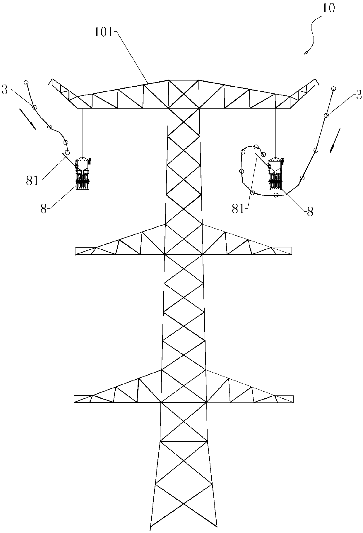
[0054] Such as figure 2 As shown, corresponding to the iron tower 10 is provided with a side cross arm 101, the two ends of the side cross arm 101 hang the situation of the guide rod type tackle 8 respectively; the helicopter 5 flies over the iron tower 10, Control the flight trajectory of the helicopter 5 so that the guide rope 3 slowly approaches the guide rod block 8 until it can pass through the guide rod of the guide rod block 8 and automatically fall into the guide rod block 8, The helicopter 5 then flies forward at normal speed.

[0055] If the guide rod 81 of the guide rod type block 8 stretches out to the outside of the iron tower 10, as figure 2 In the case on the left side of the figure, the movement track of the cross section of the guide rope 3 is used to represent the movement track of the guide rope 3 under the traction of the helicopter 5. The guide rope 3 descends from the outside of the iron tower 10 and approaches Described guide rod 81 directly slides a...

Embodiment 2

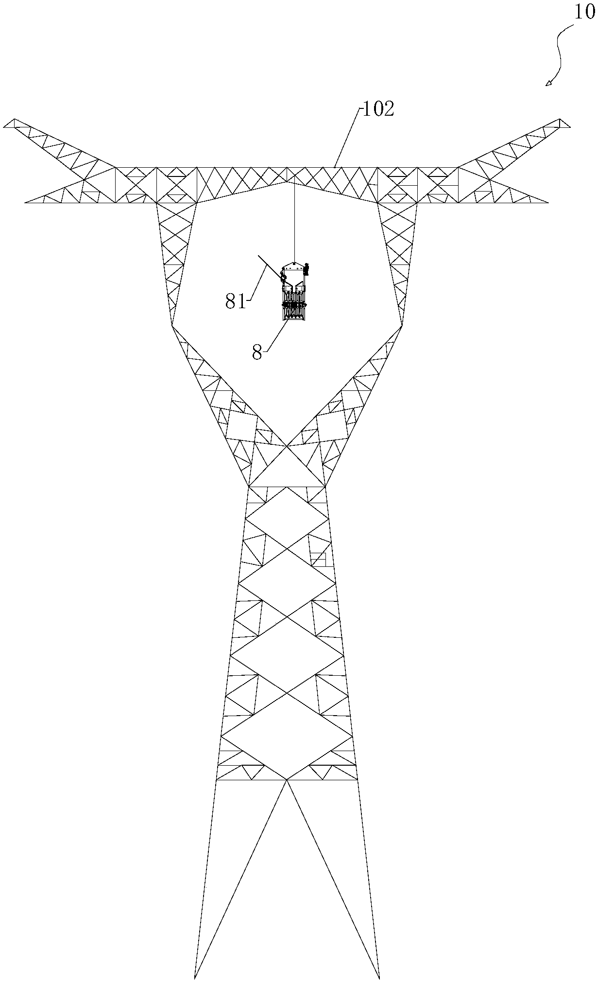
[0057] Such as image 3 As shown, corresponding to the iron tower 10 is provided with a middle phase cross arm 102, the middle part of the middle phase cross arm 102 hangs the situation of the guide rod type block 8; the guide rod type block 8 is suspended on the single circuit wine glass tower In the middle window, the helicopter 5 flies to the sky above the iron tower 10, controls the flight path of the helicopter 5, and cooperates with the operator on the iron tower 10 to operate the intermediate phase device 9 to make the intermediate phase device 9 Pass the guide rope 3 under the middle phase cross-arm 102 (that is, inside the window), and make the guide rope 3 automatically fall into the In the guide rod type block 8. Its specific implementation steps can be understood in conjunction with the part about the use method of the intermediate phaser 9 in the patent document CN 204407794 U. Here, compare Figures 4A-4IGive an example.

[0058] Figure 4A Shown as step 1, ...


PUM


Abstract

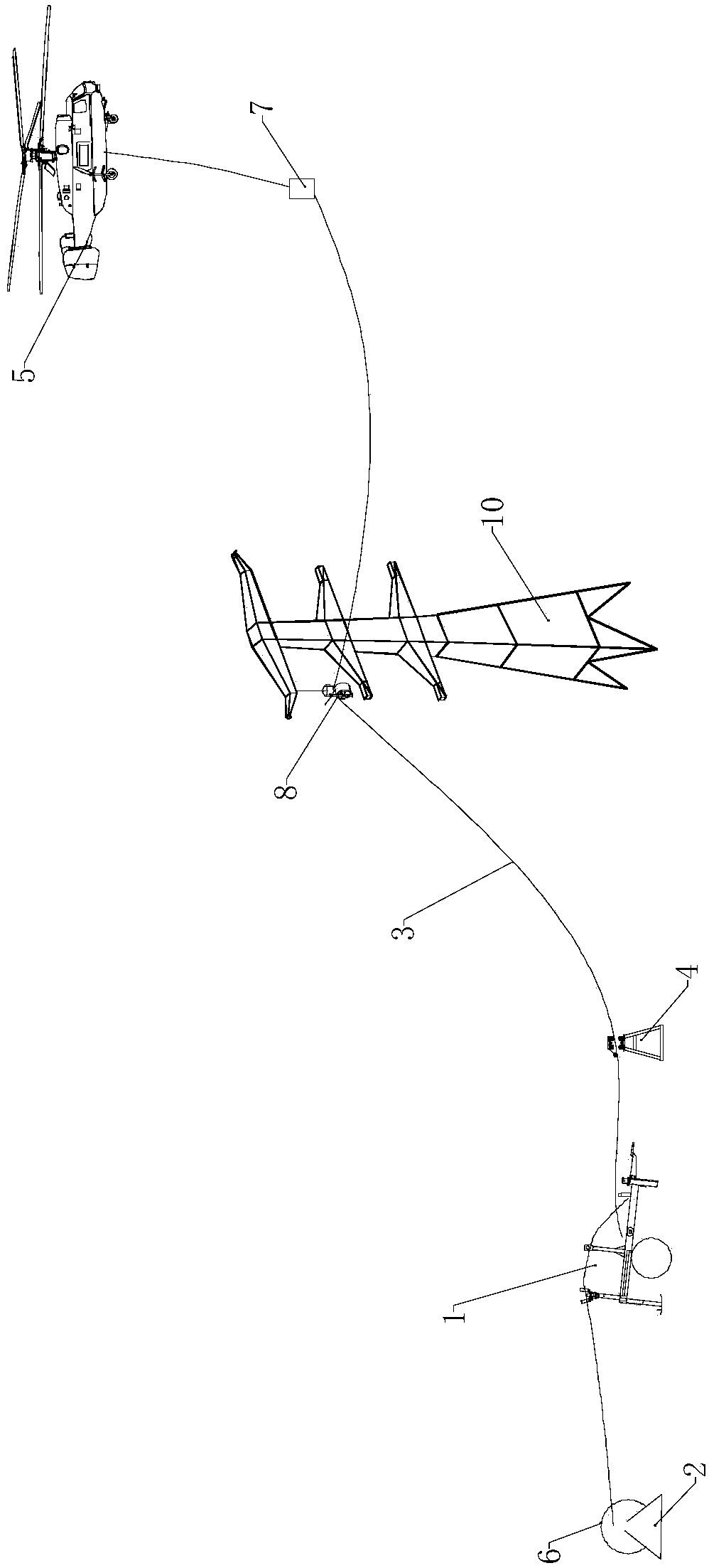
The invention discloses a method for laying out a leading rope by a helicopter. The method comprises the following steps of setting a special-purpose high speed tension machine in a tension field; placing a leading rope bobbin on a bobbin support; the rope head of the leading rope is lead out through the special-purpose high speed tension machine and line pressing pulleys arranged on the ground. A guide rod type pulley is suspended on a line laying construction position of each base tower; the helicopter drags the rope head of the leading tope and flies over a preset leading rope laying channel. The helicopter flies over the tower so that the leading rope falls into the guide rod type pulley, and the helicopter flies to the next base iron tower. If the bobbin of the leading rope is about to run out, the helicopter hovers; and then the bobbin is changed into a new leading rope bobbin in the tension field, and the helicopter continues to perform flight working until the leading rope goes through the guide rod type pulleys of all the iron towers of a line laying segment. The helicopter flies to an anchor line field at the end of the line laying segment, slowly descends and anchors the leading rope to the ground. According to the invention, a lot of cooperation work by high altitude construction personnel can be reduced so as to greatly raise the security and the construction efficiency.

Description

technical field [0001] The invention relates to the deployment of high-voltage electric wires, in particular to a method for deploying guide ropes by a helicopter. Background technique [0002] my country has a vast territory, and the distribution of energy reserves and power loads is uneven. In order to enhance the ability to optimize the allocation of power resources in a wider range and meet the growing demand for electricity in different regions, the construction of large-scale UHV power grids is developing rapidly. UHV line engineering is characterized by high transmission voltage level, large tower tonnage, high height, long span between two adjacent towers, and many crossing conductors. After the UHV iron tower is assembled and accepted, it is necessary to carry out tension setting-out construction to complete the erection of the transmission line. [0003] The method of laying out the guide (ground) wire by using construction equipment such as tractors and tensione...

Claims


Application Information

Patent Timeline
Patent Type & Authority Patents(China)
IPC IPC(8): H02G1/02H02G1/04B65H59/10
CPCB65H59/10B65H2701/35H02G1/02H02G1/04
Inventor 王浩淼吴建军李磊刘伟东王弋方平凯于翔叶子刘春田
Owner SGCC GENERAL AVIATION
Learn More