Handcart switch cabinet
A handcart-type switch and handcart technology, which is applied in the direction of pull-out switchgear, switchgear, electrical components, etc., can solve problems such as safety accident equipment, rigid deformation of the main shaft, accidents, etc., to achieve stable operation and ensure accuracy , The effect of avoiding safety accidents and equipment accidents
- Summary
- Abstract
- Description
- Claims
- Application Information
AI Technical Summary
Problems solved by technology
Method used
Image
Examples
Embodiment 1
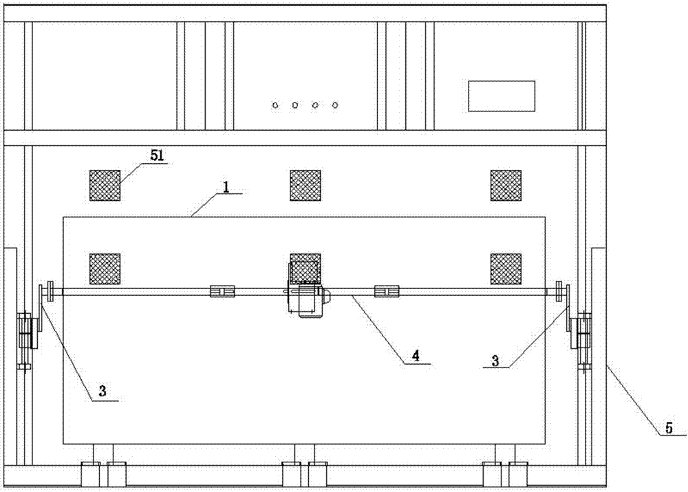
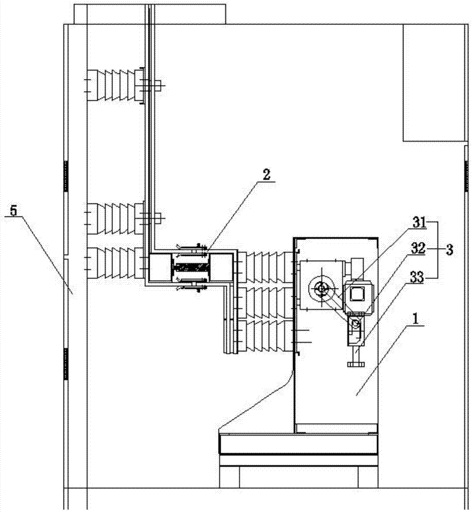
[0031] figure 1 The structural representation of the handcart type switchgear provided for the embodiment of the present invention; figure 1 with figure 2 As shown, the handcart switchgear provided in this embodiment includes: a handcart assembly, and the handcart assembly includes: a handcart 1, an isolation device and a linear motion mechanism 3, the isolation device is arranged on one side of the handcart 1, and the handcart The other side of 1 is provided with a main shaft 4, the main shaft 4 is the main shaft of the isolation device, the two ends of the main shaft 4 are respectively connected with the linear motion mechanism 3, and the linear motion mechanism 3 is used to drive the handcart 1 for horizontal movement.
[0032] The rotary motion of the main shaft 4 is converted into the horizontal linear motion of the handcart 1 through the linear motion mechanism 3, so that the isolation device on the handcart 1 also moves horizontally and linearly, which changes the ver...
Embodiment 2
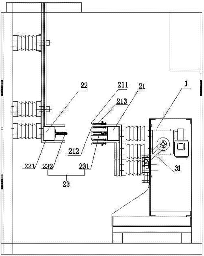
[0038] figure 2 The left view of the handcart type switchgear provided for the embodiment of the present invention; image 3 for figure 2 The structural schematic diagram of the three-phase isolating switch shown; Figure 4 The top view of the handcart type switchgear provided for the embodiment of the present invention; Figure 2-4 As shown, the isolating device is a three-phase isolating switch 2 or a circuit breaker.
[0039] The structure of the three-phase isolating switch 2 is relatively simple. When it is in the divided position, there is an insulation distance between the contacts that meets the specified requirements and an obvious disconnection mark; when it is in the closed position, it can carry the current under normal circuit conditions and within the specified time Current flow under abnormal conditions such as short circuits.
[0040] The three-phase isolating switch 2 or the circuit breaker will move horizontally and linearly with the handcart 1, which c...
Embodiment 3
[0043] Figure 5 The front view of the linear motion mechanism provided by the embodiment of the present invention; on the basis of the above embodiments, this embodiment further improves the handcart switch cabinet. Specifically, the linear motion mechanism 3 includes: crank arm 31, Slide block 32 and fixed bracket 33, one end of crank arm 31 is fixed with the end of main shaft 4, and the other end of crank arm 31 is fixed with slide block 32, and slide block 32 slides up and down along the slide rail on the fixed bracket 33.
[0044] Such as Figure 5 As shown, in the initial state, the main shaft 4 is located on the right side of the crank arm 31. When the main shaft 4 rotates counterclockwise, the force it receives can be decomposed into an upward component force and a forward component force. Since the crank arm 31 is Rigid body, so the upward component force is transmitted from the upper end of the crank arm 31 to the lower end, and pushes the slider 32 connected to the...
PUM
 Abstract
Description
Claims
Application Information
 - R&D
- Intellectual Property
- Life Sciences
- Materials
- Tech Scout
- Unparalleled Data Quality
- Higher Quality Content
- 60% Fewer Hallucinations
Browse by: Latest US Patents, China's latest patents, Technical Efficacy Thesaurus, Application Domain, Technology Topic, Popular Technical Reports.
© 2025 PatSnap. All rights reserved.Legal|Privacy policy|Modern Slavery Act Transparency Statement|Sitemap|About US| Contact US: help@patsnap.com


