
Magnetic positioning replacement device for light filter

A technology of positioning device and optical filter, applied in installation, optics, optical components, etc., can solve the problems of difficulty in meeting actual needs, large component size and weight, etc., and achieve the effect of saving development cost, simple and compact structure, and low heat.

Inactive Publication Date: 2017-02-22
ZIJINSHAN ASTRONOMICAL OBSERVATORY CHINESE ACAD OF SCI
View PDF9 Cites 2 Cited by
  • Summary
  • Abstract
  • Description
  • Claims
  • Application Information

AI Technical Summary

Problems solved by technology

In order to ensure the optical accuracy of the optical filter when it is working, the mechanical support members of the existing optical filters are usually relatively strong (the same mechanical support member is used for both the operating state and the working state of the optical filter), resulting in the size and weight of the members. Relatively large, difficult to meet actual needs

Method used


Image

  • Magnetic positioning replacement device for light filter
  • Magnetic positioning replacement device for light filter
  • Magnetic positioning replacement device for light filter

Examples


Embodiment 1

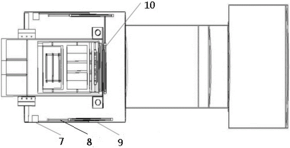
[0030] A filter magnetic positioning replacement device, such as image 3 As shown, the device is installed in the lens barrel of the main focus type telescope, including the filter storage position 7, the slide rail 8, the filter support device 9, and the filter positioning device 10; the front end of the inner wall of the lens barrel is installed in sequence The filter storage position 7 and the slide rail 8 are in a straight line. The filter support device 9 is installed in parallel on the inner wall of the lens barrel and fixed and transferred by the slide rail 8; the filter positioning device 10 is located at the front end of the camera. It forms an angle of 90° with the slide rail; the sizes of the filter support device 9 and the filter positioning device 10 just match.

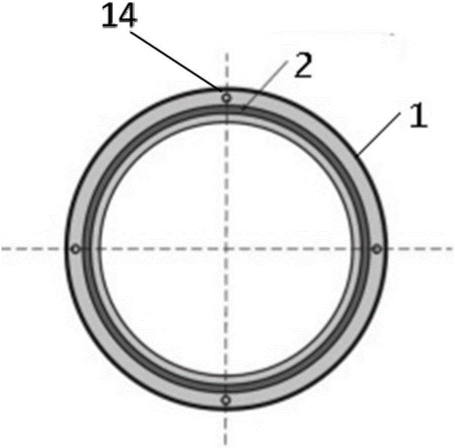
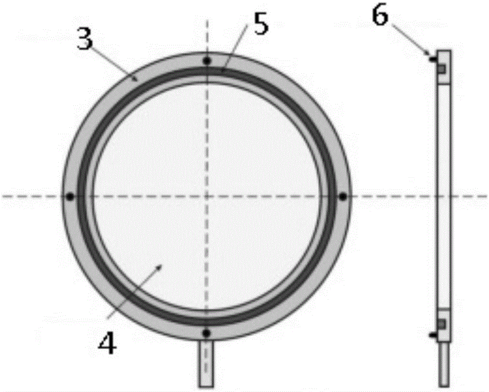
[0031] Such as figure 1 As shown, the filter positioning device 10 includes a first base 1 and a controllable electromagnet 2 installed on the first base, and in addition, a slot 14 is installed around...

Embodiment 2

[0039] Others are the same as in Embodiment 1, and the front end of the inner wall of the lens barrel is sequentially installed with two filter storage positions 7 and slide rails 8; the angle between the two positions is 180 degrees. Different types of filters are placed in each storage location to meet actual needs.

Embodiment 3

[0041] Others are the same as in Embodiment 1, and the front end of the inner wall of the lens barrel is sequentially installed with six filter storage positions 7 and slide rails 8, and the angle between two positions is 60 degrees. Different types of filters are placed in each storage location to meet actual needs.


PUM


Abstract

The invention discloses a magnetic positioning replacement device for a light filter. The device is mounted in a main focus type telescope tube, and comprises a light filter storage device 7, a sliding rail 8, light filter supporting devices 9 and a light filter positioning device 10, wherein the light filter storage device 7 and the sliding rail 8 are sequentially mounted at the front end of the inner wall of the tube and are linearly arranged; the light filter supporting devices 9 are arranged on the inner wall of the tube in parallel and are fixed and transferred by the sliding rail 8; the light filter positioning device 10 is positioned at the front end of the camera and forms an angle of 90 degrees with the sliding rail; the light filter supporting devices 9 are just matched with the light filter positioning device 10 in size.

Description

technical field [0001] The invention belongs to the application field of optical imaging observation of astronomical telescopes, and in particular relates to a magnetic positioning replacement device for optical filters. Background technique [0002] The optical filter positioning replacement device is a supporting device for uploading and replacing optical filters when astronomical telescopes carry out imaging observations. The new generation of large field of view telescopes newly developed in the world usually have a focal plane with a diameter of more than 3 degrees, a physical size of more than 300mm, a matching filter with a large diameter, and a weight of more than 5kg. Prime focus telescopes (such as image 3 Shown) relatively light-blocking area is small, and become one of the main schemes of large field of view telescope. Due to the large physical size of the optical filter device, how to install the optical filter uploading and replacement device on the main focu...

Claims


Application Information

Patent Timeline
Patent Type & Authority Applications(China)
IPC IPC(8): G02B23/00G02B7/00
CPCG02B7/006G02B23/00
Inventor 姚大志杨戟郑宪忠刘伟娄铮华园园
Owner ZIJINSHAN ASTRONOMICAL OBSERVATORY CHINESE ACAD OF SCI
Learn More