
Broadband large dynamic signal high-precision measurement device and method

A wide-band, large dynamic technology, applied in the field of communication, can solve the problems of low test accuracy, deterioration of modulation signal measurement accuracy, lack of self-adaptive configuration demodulation channel state parameters of the signal to be tested, etc., to solve noise and distortion, Achieve high-precision measurement and optimize the effect of demodulation bandwidth

Active Publication Date: 2017-02-22
THE 41ST INST OF CHINA ELECTRONICS TECH GRP
View PDF7 Cites 6 Cited by
  • Summary
  • Abstract
  • Description
  • Claims
  • Application Information

AI Technical Summary

Problems solved by technology

When the input signal power of the measurement device is 0dBm, and the demodulation bandwidth is 1MHz, the abnormal response due to the harmonic distortion of the ADC usually exceeds -70dBc. According to the theoretical formula of the influence of random noise on the measurement results, the precise modulation parameters can be realized. Extraction requires a signal-to-noise ratio of at least 37dB. At this time, the signal-to-noise ratio of the signal to be tested and the false response is only 14dB. The superposition of abnormal response signals and random noise seriously deteriorates the measurement accuracy of the modulated signal.
[0006] The frequency domain analysis method commonly used at present does not have a setting method for adaptively configuring the demodulation path state parameters according to the signal to be tested, lacks flexibility, and the test accuracy is not high, which does not meet the measurement test requirements
In the process of use, testers need to manually adjust channel parameters according to the characteristics of the signal to be tested, such as modulation rate, sideband amplitude, etc., based on test experience. Different channel setting parameters will get different test results. Therefore, this type of test method has the advantages of Larger limitations

Method used


Image

  • Broadband large dynamic signal high-precision measurement device and method
  • Broadband large dynamic signal high-precision measurement device and method
  • Broadband large dynamic signal high-precision measurement device and method

Examples


Embodiment Construction

[0045] The following will clearly and completely describe the technical solutions in the embodiments of the present invention with reference to the accompanying drawings in the embodiments of the present invention. Obviously, the described embodiments are only some, not all, embodiments of the present invention. Based on the embodiments of the present invention, all other embodiments obtained by persons of ordinary skill in the art without making creative efforts belong to the protection scope of the present invention.

[0046] Traditional spectrum analyzers can test signal spectrum parameters, but they do not have the ability to test modulation parameters, especially broadband modulation parameters. They lack flexibility, low test accuracy, and do not meet the requirements of metrology testing.

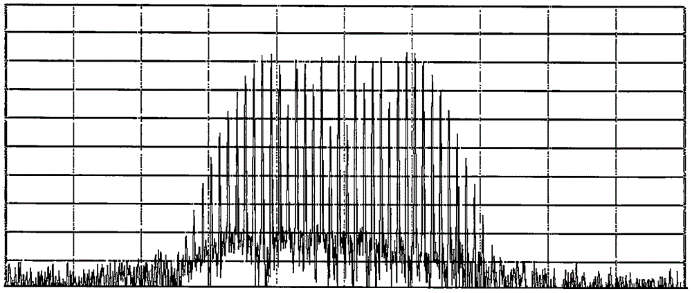
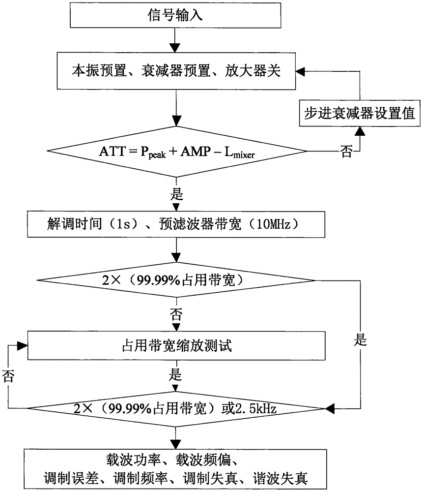
[0047] Such as figure 1As shown, the present invention proposes a wide-band large dynamic signal high-precision measurement device including three functional units, namely a signal r...


PUM


Abstract

The invention provides a broadband large dynamic signal high-precision measurement device and method, and solves the problems that the current widely used frequency domain analysis method has no setting method for self-adaptively configuring demodulation circuit state parameters according to signals to be measured, lacks flexibility, has low test precision and does not meet the measurement test requirements. According to the broadband large dynamic signal high-precision measurement device and method, the pretest characteristic parameters of the signals to be measured of the test device are utilized, and an automatic rule processor is created to optimizing configuration of the channel gain value and the demodulation bandwidth value of the test device so that high-precision measurement of broadband large dynamic signals can be realized.

Description

technical field [0001] The invention relates to the communication field, in particular to a high-precision measurement device for wide-band large dynamic signals, and also relates to a high-precision measurement method for wide-band large dynamic signals. Background technique [0002] With the rapid development of military communications and civilian communications, broadband signal generation technology has also developed rapidly, which is characterized by wider and wider signal frequency bands and more and more complex modulation systems. Typical characteristic parameters include signal frequency parameters and amplitude parameters. and modulation parameters, etc. [0003] At present, the test of signal frequency and amplitude parameters mostly adopts frequency domain analysis test method, but the test process of modulation parameters is more complicated, and it is necessary to optimize the settings of frequency domain analysis test state parameters such as center frequenc...

Claims


Application Information

Patent Timeline
IPC IPC(8): G01R19/00G01R23/02G01R23/16G01R29/00G01R29/06
CPCG01R19/00G01R23/02G01R23/16G01R29/00G01R29/06
Inventor 许建华杜以涛杜会文张超赵永志张峰向长波崔素玲张明岳
Owner THE 41ST INST OF CHINA ELECTRONICS TECH GRP
Learn More