Method for zeroing initial null voltage of bridge sensor

A bridge sensor, initial zero technology, applied in the field of sensors, can solve the problems of inability to achieve accurate measurement, saturation of operational amplifiers, weak voltage signals, etc., to achieve the effect of improving high overload resistance, high reception, and increasing service life

Active Publication Date: 2017-02-22
苏州戎维邦信息技术有限公司
View PDF5 Cites 5 Cited by
  • Summary
  • Abstract
  • Description
  • Claims
  • Application Information

AI Technical Summary

Problems solved by technology

Usually, because the voltage signal output by the cantilever beam bridge sensor is very weak, the voltage signal needs to be amplified subsequently. If the initial zero voltage is too large and the operational amplifier is saturated, the requirements for accurate measurement cannot be met.

Method used


Image

  • Method for zeroing initial null voltage of bridge sensor
  • Method for zeroing initial null voltage of bridge sensor
  • Method for zeroing initial null voltage of bridge sensor

Examples


Embodiment 1

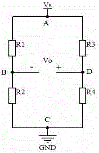
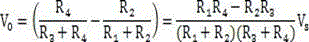
[0033] The present invention provides a method that can stably, reliably and quickly complete the zeroing of the bridge sensor. The specific implementation is as follows:

[0034] The resistances of the four arms of the Wheatstone bridge are , , , , using DC power supply, the power supply voltage is , the zero output voltage is , when the sensor input signal is zero, there is

[0035]

[0036] when , that is, there is a zero voltage, and the sensor needs to be zeroed.

[0037] According to the actual situation, the present invention adopts the manual hardware zeroing method to complete the zeroing work in the production process of the sensor. During the zeroing process, the average resistance value of the arm resistance of the Wheatstone bridge needs to be measured, and the zeroing resistance is calculated by the formula The size of the zero-adjustment resistance should be determined reasonably, so that the zero-adjustment resistance R can be combined with as ...

example 1

[0064] Example 1: In the sensor production process, the measured input resistance , output resistance , the initial zero voltage , The sensor is powered by a 3.3V DC power supply.

[0065] by the formula

[0066]

[0067]

[0068] Select 32 from the zeroing resistor sequence 、18 , 1.8 The resistors are connected in series to form a zeroing resistor R=51.8 .

example 2

[0069] Example 2: In the sensor production process, the measured input resistance , output resistance , the initial zero voltage , The sensor is powered by a 3.3V DC power supply.

[0070] by the formula

[0071]

[0072]

[0073] Pick 100 from the zeroing resistor sequence The resistance directly gets the zeroing resistance R=100 .

[0074] Connect the combined resistor R in parallel to a bridge with a higher potential (such as Figure II ), the measured initial output voltage of the bridge sensor after zeroing is less than 1 . After fixing the parallel resistance R, it can be packaged, and the zero adjustment work is completed, and then the subsequent work such as sensor calibration is performed.


PUM


Abstract

The invention discloses a method for zeroing the initial null voltage of a bridge sensor. The method comprises a step 1 of accurately measuring the Wheatstone bridge initial null voltage, the input resistance and the output resistance of the bridge sensor before the bridge sensor is fabricated and packaged; a step 2 of calculating the average resistance of the bridge sensor; a step 3 of calculating zeroing resistance connected in parallel with an arm with higher potential; a step 4 of forming a zeroing resistor with the required resistance by means of series connection or parallel connection from a zeroing resistor sequence; a step 5 of connecting the zeroing resistor in parallel to the arm with the higher potential, and completing the package test of the bridge sensor. In the invention, an external zeroing method of the sensor is transformed into an internal zeroing method, and a zeroing test and production are carried out by a sensor manufacturer. When using the bridge sensor, the user does not need to zero the bridge sensor anymore. A high receiving degree is achieved. Compared with the zeroing of an external parallel potentiometer, the method is stable and reliable in connection and prolongs a service life.

Description

technical field [0001] The invention relates to the field of sensors, in particular to a method for zeroing the initial zero voltage of a bridge sensor. Background technique [0002] With the further development of microelectronics technology and computers, the application of micro-cantilever beam bridge sensors is becoming more and more common, and is widely used in aerospace, aviation, petrochemical, power machinery, biomedical engineering, meteorology, geology, seismic measurement, etc. field. At this time, it is particularly important to realize accurate measurement and real-time monitoring of the piezoresistive bridge sensor. Bridge sensor is an important family of sensors. Many physical quantities such as pressure, load, strain, acceleration, displacement, etc. are measured, and bridge-type sensors are often used. Due to various reasons (such as the uneven distribution of ions in the manufacture of bridge arm resistance by MEMS technology), when the input is measured...

Claims


Application Information

Patent Timeline
Patent Type & Authority Applications(China)
IPC IPC(8): G01D18/00
CPCG01D18/00
Inventor 马少杰
Owner 苏州戎维邦信息技术有限公司
Why Eureka
Try Eureka