
Mounting structure of range hood motor and range hood

A technology of installation structure and motor, which is applied in the field of range hoods, can solve problems such as difficult processing technology, increased air resistance, and increased noise, and achieve the effects of low processing technology requirements, reduced flow noise, and reduced vibration noise

Inactive Publication Date: 2017-02-22
GUANGDONG MIDEA KITCHEN APPLIANCES MFG CO LTD +1
View PDF7 Cites 8 Cited by
  • Summary
  • Abstract
  • Description
  • Claims
  • Application Information

AI Technical Summary

Problems solved by technology

[0004] However, the four legs of the motor bracket in the first solution can only play a supporting role in two directions due to the strap-like distribution, so the rigidity is small, and the split design is prone to errors during installation and positioning. As a result, the concentricity of the shaft after the motor is installed is not good
In addition, during the long-term operation and transportation of the split motor bracket, due to the uneven force on the bracket, the bracket is easily deformed, which easily causes the deformation of the volute back plate, the concentricity of the impeller of the centrifugal fan becomes worse, and the noise becomes louder
Although the second scheme has a good shock absorption effect, due to the use of two motor brackets, the structure is complex, the cost is high, and the actual installation process is complicated, which is not conducive to production. Concentricity
The most important of these is that the use of two or more motor brackets will seriously increase air resistance, which will easily cause flow-induced vibration (vibration caused by fluid flow)

Method used


Image

  • Mounting structure of range hood motor and range hood
  • Mounting structure of range hood motor and range hood
  • Mounting structure of range hood motor and range hood

Examples


Embodiment Construction

[0035] Specific embodiments of the present invention will be described in detail below in conjunction with the accompanying drawings. It should be understood that the specific embodiments described here are only used to illustrate and explain the present invention, and are not intended to limit the present invention.

[0036] In the present invention, in the case of no contrary description, the used orientation words such as "up, down, left and right" usually refer to the up, down, left and right shown in the accompanying drawings; "inside and outside" Refers to the inside and outside of the outline of each part itself.

[0037] As introduced in the background art, the centrifugal fan can generate relatively large wind pressure and air volume, but the noise generated by the centrifugal fan is also a difficult problem to solve. The noise of the centrifugal fan is mainly caused by vibration and air flow. Among them, the motor is the main source of noise in the centrifugal fan. ...


PUM


Abstract

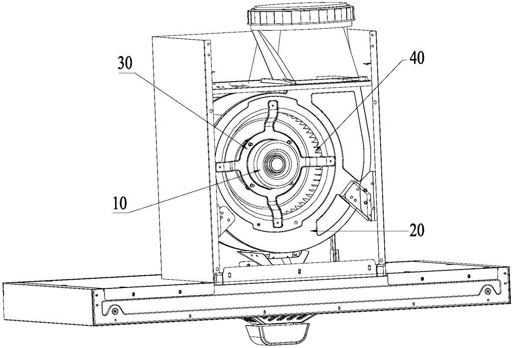
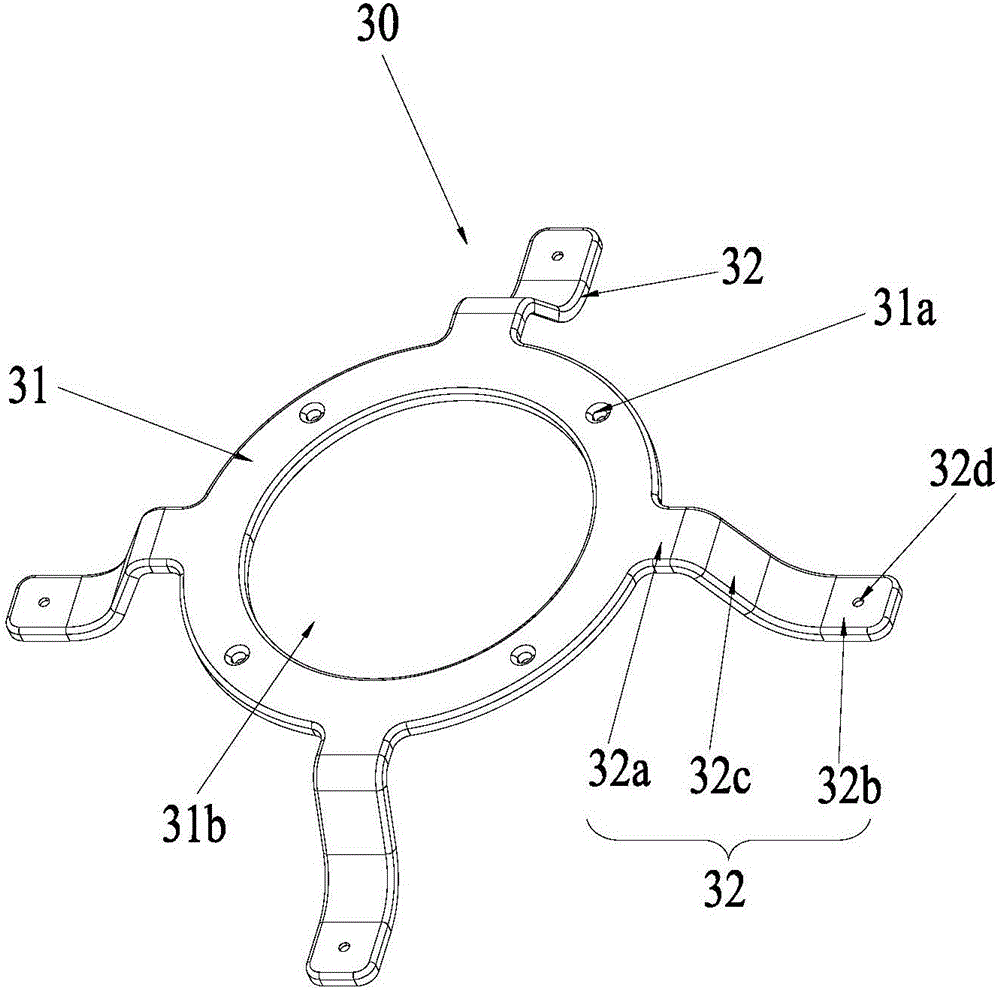
The invention relates to the field of range hoods, and discloses a mounting structure of a range hood motor and a range hood. The mounting structure of the range hood motor comprises the motor (10), a fan volute (20) and a motor bracket (30), wherein the motor is fixed to the motor bracket; the motor bracket comprises a mounting body (31) and a plurality of supporting feet (32) fixed to the fan volute; and the plurality of supporting feet integrally extend out of the mounting body and are uniformly distributed on the mounting body. According to the mounting structure of the range hood motor provided by the invention, the motor bracket is integrally formed, so that the structure is simple, the cost is relatively low, the requirement of the processing technology is low, and the assembly is simple during mass production; the integrally formed structure is adopted, so that the plurality of supporting feet are stressed at the same time and are not liable to deform, and vibration noise caused by nonuniform stress can be reduced; and besides, the supporting feet are uniformly distributed on the mounting body, so that vortex generated by airflow when entering an impeller from a back plate of the fan volute can be effectively reduced, and the flowing noise is reduced.

Description

technical field [0001] The invention relates to a range hood, in particular to a motor installation structure of the range hood and the range hood. Background technique [0002] With the improvement of people's living standards, the range hood has almost become an indispensable electrical appliance in the kitchen as a kitchen appliance for purifying the kitchen environment. The range hood is installed above the stove, and is used to quickly suck away the waste burned by the stove and the oil fume harmful to the human body produced during the cooking process, and discharge it to the outside to reduce pollution and purify the air. The fan system is the core power system of the range hood, and the commonly used fan system is a centrifugal fan. The centrifugal fan is mainly composed of a motor, an impeller and a fan volute, which can generate large wind pressure and air volume, and the motor is installed through the motor bracket. [0003] Generally, there are two kinds of mot...

Claims


Application Information

Patent Timeline
Patent Type & Authority Applications(China)
IPC IPC(8): F24C15/20
CPCF24C15/20
Inventor 闫亮何新奎蒋济武余悦泳
Owner GUANGDONG MIDEA KITCHEN APPLIANCES MFG CO LTD
Learn More