
Tire type lining structure between tunnel and shield lining segment and method

A lining segment and lining technology, applied in tunnel lining, tunnel, wellbore lining and other directions, can solve the problems of uneven stress on shield lining segments, high air tightness requirements for inflatable tire bags, and easy deformation, etc. Strong anti-deformation ability, stable pressure, and the effect of mitigating disturbance

Active Publication Date: 2017-02-22
CHINA THREE GORGES UNIV
View PDF7 Cites 18 Cited by
  • Summary
  • Abstract
  • Description
  • Claims
  • Application Information

AI Technical Summary

Problems solved by technology

In the excavated tunnel, the stress distribution of the surrounding rock is uneven, which will lead to uneven stress on each part of the shield lining segment and easy deformation. Considering the above problems, a shield lining that can act on the The tire-type lining structure of the segment, but considering the high airtightness requirements of the inflatable tire bag and the instability of long-term use, the patent uses water-saturated sand as the filler

Method used


Image

  • Tire type lining structure between tunnel and shield lining segment and method
  • Tire type lining structure between tunnel and shield lining segment and method
  • Tire type lining structure between tunnel and shield lining segment and method

Examples


Embodiment 1

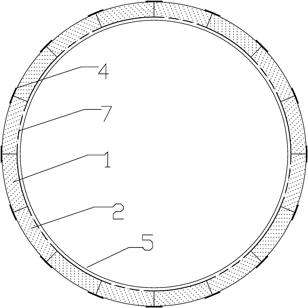
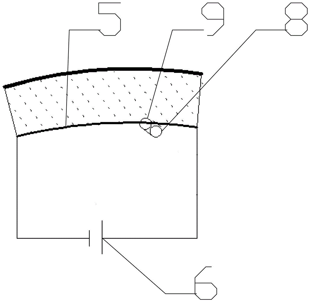
[0030] Such as Figure 1-3 , used for the tire-type lining structure between the tunnel and the shield lining segment, which includes a lining bladder 1, the lining bladder 1 is made of rubber material, and the lining bladder 1 is attached to the lining segment 7 The outer wall of the lining bladder 1 is filled with water-saturated sand 2, and the inner wall of the lining bladder 1 is smooth, which facilitates the flow of water-saturated sand. Each lining bladder 1 is densely paved with the splicing of the lining segment 7.

[0031] Further, the lining tire sac 1 on the outside of each lining segment 7 is formed into an independent tire chamber 3, and each tire chamber 3 is not communicated with each other, and the position where the lining tire sac 1 is in direct contact with the rock and soil is protected by a shield The mechanism is covered with a waterproof geomembrane 4 .

[0032] Further, each of the lining bladders 1 is equipped with a vibrating plate 5, which can impr...

Embodiment 2

[0036] A construction method for a tire-type lining structure between a tunnel and a shield lining segment, which includes the following steps:

[0037] Step 1: Carry out long-term prediction of surrounding rock creep through construction monitoring and numerical simulation of tunnel surrounding rock deformation, determine the position with large deformation of surrounding rock, and perform joint support of lining segment 7 and tire lining at this position;

[0038] Step 2: Fit and assemble the lining tire bag 1 filled with dry sand and the lining segment 7, and install the automatic pressure relief device before sending it into the shield machine, and the mechanical claws of the shield machine will carry the lining tire The lining segment 7 of the bladder 1 is assembled to the corresponding position;

[0039] Step 3: For parts with large deformation of the surrounding rock, inject water into the lining bladder 1 filled with dry sand and vibrate, and the automatic pressure rel...


PUM


Abstract

The invention discloses a tire type lining structure between a tunnel and a shield lining segment and a method. The tire type lining structure comprises a lining tire sacs, wherein the lining tire sac is made of a rubber material; the lining tire sacs are fitted to the outer wall of the lining segment and are filled with water saturated sand; the inner parts of the lining tire sacs are smooth and facilitate the flowing of the water saturated sand; and all the lining tire sacs are closely laid with the splicing of the lining segments. By means of pre-deformation of the tire sacs, the deformation of the shield lining segments is prevented, so that long-term stability and safety of the shield lining segments in the tunnel can be guaranteed.

Description

technical field [0001] The invention relates to the field of tunnel engineering, in particular to a tire-type lining structure and method used between tunnels and shield lining segments. Background technique [0002] With the rapid development of tunnel engineering, the application of shield machines is becoming more and more extensive, and there will be some difficulties in the construction process. In the excavated tunnel, the stress distribution of the surrounding rock is not uniform, which will lead to uneven stress on each part of the shield lining segment, which is prone to deformation. Considering the above problems, a shield lining that can act on the The tire-type lining structure of the segment, but considering the high airtightness requirements of the pneumatic tire bag and the instability of long-term use, so the patent uses water-saturated sand as the filler. Contents of the invention [0003] The purpose of the present invention is to provide a tire-type lin...

Claims


Application Information

Patent Timeline
IPC IPC(8): E21D11/08E21D11/00
CPCE21D11/00E21D11/08
Inventor 刘杰颜溧洲雷岚王连王晨光方永德黄茜王飞黄慧萍雒培铭
Owner CHINA THREE GORGES UNIV
Learn More