Portable double-layer coiled tubing sand pumping device and technology

A convenient, tubing technology, used in wellbore/well components, earth-moving drilling, etc., can solve the problems of affecting gas production, easy wear, difficult installation, etc., achieving good working stability, easy installation and use, sand pumping Efficiency improvement effect

Active Publication Date: 2019-01-25
LUZHOU CHANGJIANG GASOLINEEUM ENG MACHINERYCO
View PDF8 Cites 0 Cited by
  • Summary
  • Abstract
  • Description
  • Claims
  • Application Information

AI Technical Summary

Problems solved by technology

[0002] After a period of time, the gas wells used to exploit natural gas will be blocked by sand bridges and sedimentation due to sand deposition and crystallization in the wells, which will affect the gas production rate or even stop gas production at all. It goes smoothly; in the past, the sand pumping methods used in gas wells mainly include gas lift sand pumping and foam sand pumping. The former injects liquid nitrogen and compressed gas into the well through the choke manifold, and the gas expands to bring out sand from the tubing. ;The latter sends the coiled tubing into the well through the coiled tubing drum and driving device, coiled tubing, water pump, injection head, etc., injects the foam discharge agent into the well, and after forming foam, blows the foam out through the air compressor to achieve the purpose of sand discharge; Both of these two methods have medium expansion, which will damage the formation, which is not conducive to subsequent production, and the amount of sand discharge is uncontrollable, with limited sand discharge efficiency and high energy consumption. Later, double-layer coiled tubing sand pumping appeared. The one disclosed in 201610366691 sends the flushing and plugging nozzle down the well, and uses high-pressure water to disperse the sand, and at the same time pushes the liquid inlet sleeve on the flushing and blocking nozzle to move backward. Under the action, the check valve in the plugging nozzle is flushed open, enters the annular space between the inner pipe and the outer pipe, and then the coiled tubing is lifted, and the sand liquid in the annular space is discharged from the sand discharge pipe by using the air pressure in the well; The structure of the nozzle is relatively complex, difficult to install, high cost, and there are many moving parts such as the liquid inlet sleeve, which are easy to wear and have poor working condition stability. In addition, coiled tubing needs to be lifted back and forth, and the well depth is more than 1,000 meters, which also affects Sand pumping efficiency

Method used


Image

  • Portable double-layer coiled tubing sand pumping device and technology
  • Portable double-layer coiled tubing sand pumping device and technology
  • Portable double-layer coiled tubing sand pumping device and technology

Examples


Embodiment Construction

[0016] The present invention will be described in further detail below in conjunction with the accompanying drawings.

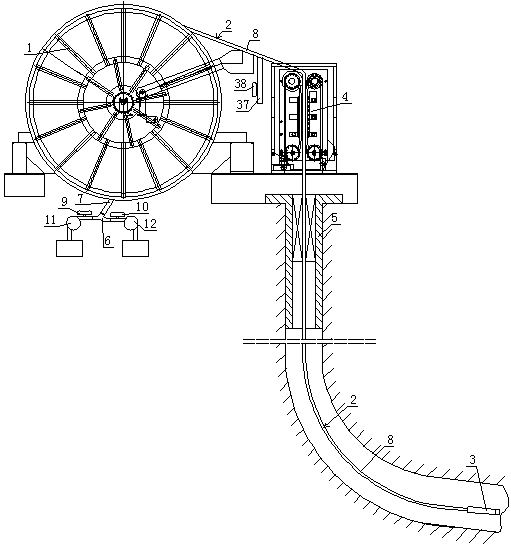
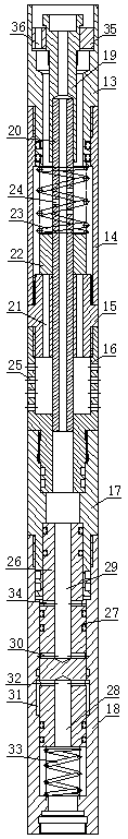
[0017] Such as Figure 1 to Figure 3 As shown, the portable double-layer coiled tubing sand pumping device of the embodiment of the present invention includes a drum 1, a motor and a reducer (not shown) as a driving device, a coiled tubing 2 wound on the drum 1, and a coiled tubing for conveying Injection head 4, blowout preventer 5 placed at the wellhead, sand washing nozzle 3; coiled tubing 2 includes inner pipe 7 and outer pipe 8, the space between the inner pipe 7 and the outer pipe 8 is an annulus, and the rear end of the annulus passes through the outer The tube 8 covers the inner tube 7 and closes; the rear end of the inner tube 7 is located outside the outer tube 8, and the rear end of the inner tube 7 is connected with a three-way joint 6, and the two inlet pipes of the three-way joint 6 are provided with control valves 9 and 10 , one inlet pipe is ...


PUM


Abstract

The invention discloses a portable sand pumping device using a double-layer continuous oil pipe. The portable sand pumping device comprises a roller, a drive device, the continuous oil pipe, an injection head blowout preventer and a sand flushing sprayer, wherein the continuous oil pipe comprises an inner pipe and an outer pipe, an annulus is arranged between the inner pipe and the outer pipe, the rear end of the annulus is sealed, a tee joint is connected to the rear end of the inner pipe, each of the two inlet pipes of the tee joint is provided with a control valve, one inlet pipe of the tee joint is connected with a sand flushing medium pump, and the other inlet pipe of the tee joint is connected with a sand discharge air pump; the sand flushing sprayer comprises an inner hole and an upper connecting pipe, a connecting pipe, a sleeve, a sand inlet pipe, a transition pipe and a sprayer seat which are sequentially fixedly connected, an inner pipe connector is arranged in the upper connecting pipe, the front end of the outer pipe is connected with the upper connecting pipe, and the front end of the inner pipe is connected with the inner pipe connector; a sand discharge pipe communicated with the annulus is connected to the outer pipe and provided with a valve. The invention further provides a sand pumping process using the double-layer continuous oil pipe. The portable sand pumping device is simple in structure, convenient to mount and use, low in cost, less prone to abrasion, good in working condition stability and high in sand pumping efficiency.

Description

technical field [0001] The invention relates to a double-layer coiled tubing sand pumping device and technology for gas wells. Background technique [0002] After a period of time, the gas wells used to exploit natural gas will be blocked by sand bridges and sedimentation due to sand deposition and crystallization in the wells, which will affect the gas production rate or even stop gas production at all. It goes smoothly; in the past, the sand pumping methods used in gas wells mainly include gas lift sand pumping and foam sand pumping. The former injects liquid nitrogen and compressed gas into the well through the choke manifold, and the gas expands to bring out sand from the tubing. ;The latter sends the coiled tubing into the well through the coiled tubing drum and driving device, coiled tubing, water pump, injection head, etc., injects the foam discharge agent into the well, and after forming foam, blows the foam out through the air compressor to achieve the purpose of sa...

Claims


Application Information

Patent Timeline
Patent Type & Authority Patents(China)
IPC IPC(8): E21B27/00
CPCE21B27/00
Inventor 成心建费克林杨昌平
Owner LUZHOU CHANGJIANG GASOLINEEUM ENG MACHINERYCO
Why Eureka
Try Eureka