
High-strength special-shaped channel steel

A special-shaped groove, high-strength technology, applied in the direction of the wing frame, etc., to improve processing efficiency, improve product quality and production efficiency, and improve the effect of airtight function

Active Publication Date: 2018-06-15
胡圣伟
View PDF9 Cites 0 Cited by
  • Summary
  • Abstract
  • Description
  • Claims
  • Application Information

AI Technical Summary

Problems solved by technology

[0004] But there is following defect in a kind of airtight door frame structure disclosed in the above-mentioned patent: the structural form disclosed by CN204225708U actually realizes that the thin steel plate is folded 2 to 3 times by a folding machine, and is only suitable for the outer wrapping edge of the concrete door

Method used


Image

  • High-strength special-shaped channel steel
  • High-strength special-shaped channel steel
  • High-strength special-shaped channel steel

Examples


Embodiment Construction

[0025] The present invention will be described in detail below with reference to the accompanying drawings and examples. It should be noted that, in the case of no conflict, the embodiments in the present application and the features in the embodiments can be combined with each other.

[0026] In the description of the present invention, the terms "longitudinal", "transverse", "upper", "lower", "front", "rear", "left", "right", "middle", "vertical", " The orientations or positional relationships indicated by "horizontal", "top", "bottom", etc. are based on the orientations or positional relationships shown in the drawings, and are only for the convenience of describing the present invention rather than requiring that the present invention must be constructed and operated in a specific orientation, Therefore, it should not be construed as limiting the invention. The terms "connected" and "connected" used in the present invention should be understood in a broad sense, for examp...


PUM

PropertyMeasurementUnit
radiusaaaaaaaaaa
radiusaaaaaaaaaa
thicknessaaaaaaaaaa

Abstract

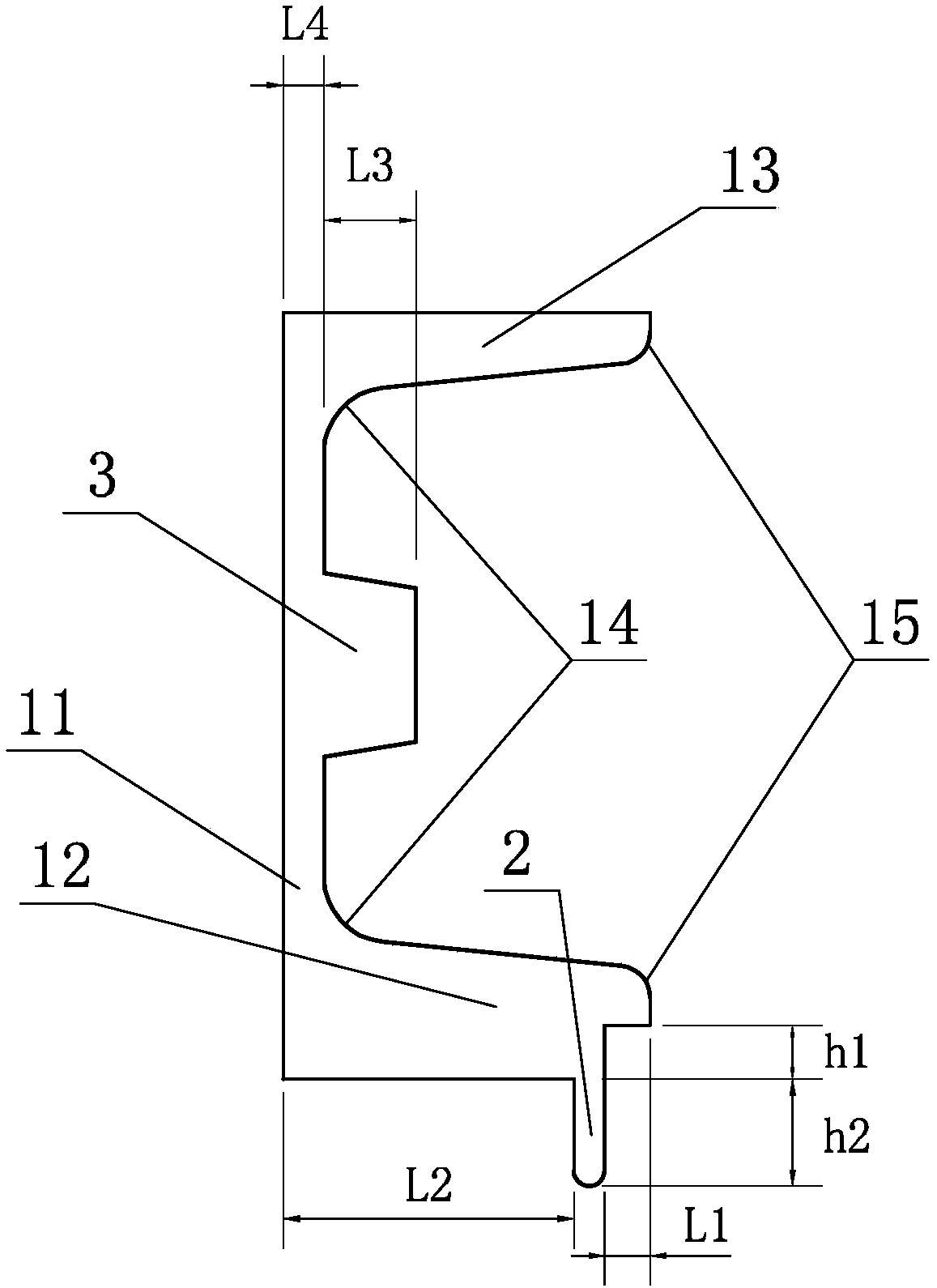
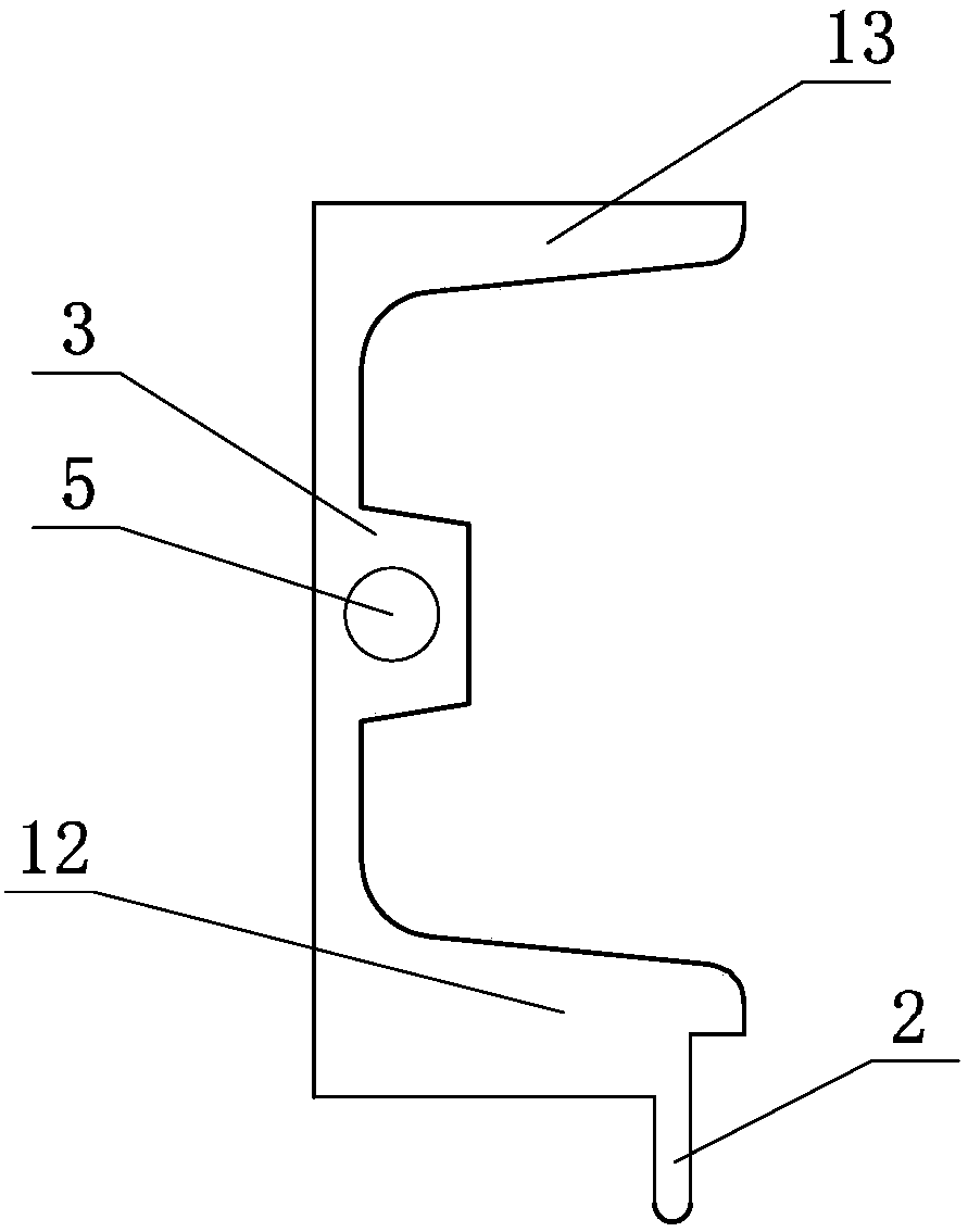
The invention provides a high strength profiled channel steel comprising a channel steel body; the channel steel body comprises an upper leg, a lower leg and a waist; the waist is connected between the upper leg and the lower leg; the upper leg and the lower leg are vertical to the waist; the channel steel body also comprises an embedded press strip which is connected to the upper leg or the lower leg; the thickness of the upper leg or the lower leg at the right side of the embedded press strip is less than that of the upper leg or the lower leg at the left side of the embedded press strip; the channel steel body also comprises a reinforced rib which is installed at the waist. By means of the high strength profiled channel steel, the door leaf production technology is simplified, the product quality and production efficiency are increased, the resistance of door leaves is enhanced and the closing reliability is increased; the high strength profiled channel steel has high promotion value.

Description

technical field [0001] The invention relates to the field of building materials, in particular to a high-strength special-shaped channel steel, which is especially suitable for use on the door of protective equipment in underground protective engineering. Background technique [0002] The door leaf structure of the protective equipment door in the existing protective engineering has been designed for many years to weld the inner panel of the door leaf + embedded pressure strip + channel steel on the side of the standard channel steel to form the supporting surface for the door leaf and the door frame to fit together. One of its functions is to embed the seal to seal after compression, and the other is to form the skeleton frame of the door leaf structure. For doors with protective and airtight function requirements, this structural part must be provided. Since the door leaf is lap-welded sequentially by the embedded bead + inner panel + channel steel, not only the workload i...

Claims


Application Information

Patent Timeline
Patent Type & Authority Patents(China)
IPC IPC(8): E06B3/14
CPCE06B3/12
Inventor 胡圣伟
Owner 胡圣伟
Learn More