Feedback transmission method and device
A technology for transmission method and feedback information, applied in the field of feedback transmission method and device, capable of solving problems such as feedback resource overlap
- Summary
- Abstract
- Description
- Claims
- Application Information
AI Technical Summary
Problems solved by technology
Method used
Image
Examples
Embodiment 1
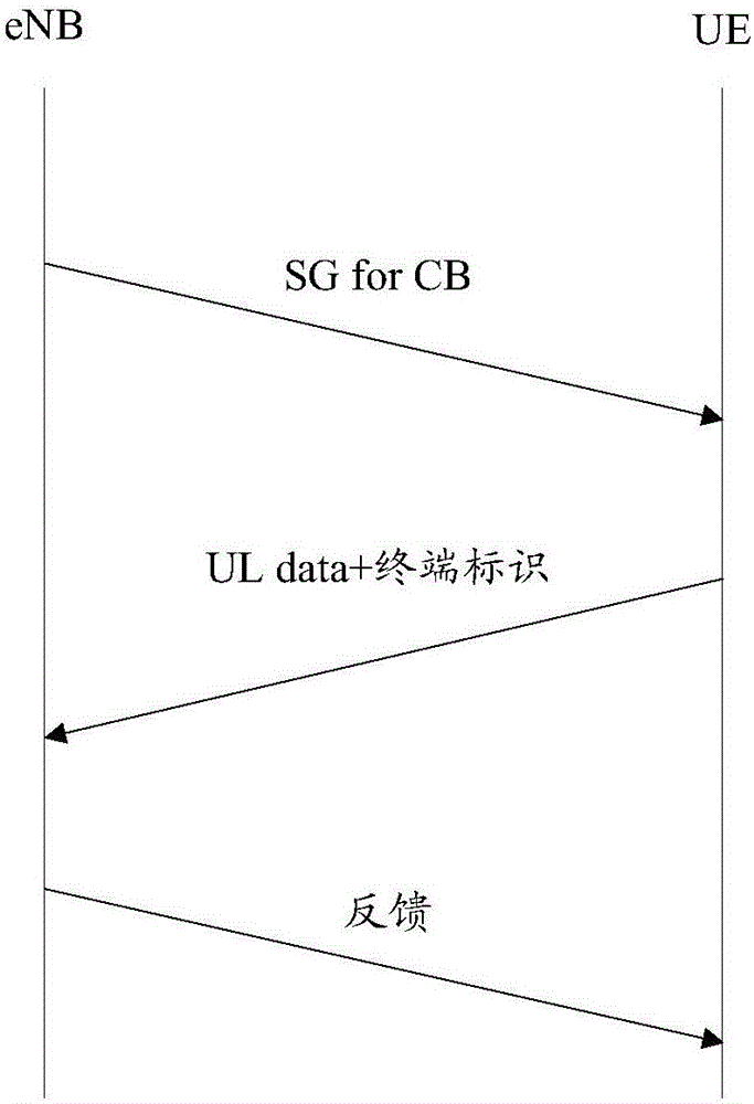
[0090]In this embodiment, the base station allocates X (eg, 10) terminals using uplink autonomous transmission to use Y (eg, 2) PRB shared resources, and the X terminals randomly use pilot cyclic shift in the Y PRBs. Specifically, the base station allocates Y PRB shared resources through a group RNTI scrambling CRC UL grant, and X terminals obtain Y PRBs that can be used through group RNTI descrambling, and X terminals do not know each other's existence .
[0091] UE1 and UE2 among the X terminals use the same cyclic shift. Since the uplink data is transmitted on the same Y PRB shared resources at the same time, the base station only demodulates the data and terminal identification information of UE1 (for example, the power of UE1 is higher than strong, or the channel condition of UE1 is better), which is equivalent to transparent transmission of UE2 and the base station does not find UE2.
[0092] The base station calculates the PHICH resource carrying the feedback ACK infor...
Embodiment 2
[0100] In this embodiment, the base station allocates X (such as 100) terminals that use uplink autonomous transmission to use Y (such as 20) PRB shared resources, wherein Y PRBs are divided into Y2 (such as 5) Shares of resources. Specifically, the base station allocates Y1 PRB shared resources through a group RNTI scrambled CRC UL grant, and X1 (such as 20) terminals obtain Y1 usable PRBs through group RNTI descrambling, and the base station also provides each terminal Terminal identification information CB_UE ID is allocated. The X1 terminals do not know each other's existence. X1 terminals randomly use pilot cyclic shift in Y1 PRBs. Similar X2 terminals randomly use pilot cyclic shift in Y2 PRBs.
[0101] UE1 and UE2 among the X1 terminals use the same cyclic shift. Since the uplink data is transmitted on the same Y1 PRB shared resources at the same time, the base station only demodulates the data and terminal identification information of UE1 (for example, the power of...
Embodiment 3
[0109] In this embodiment, the base station allocates X (eg, 10) terminals using uplink autonomous transmission to use Y (eg, 10) PRB shared resources, and the X terminals randomly use pilot cyclic shift in the Y PRBs. Specifically, the base station allocates Y PRB shared resources through a group RNTI scrambling CRC UL grant, and X terminals obtain Y PRBs that can be used through group RNTI descrambling, and X terminals do not know each other's existence . Each terminal uses the shared resources at the granularity of Y1 (for example, 2) PRBs.
[0110] UE1 among the X terminals uses the second shared resource of Y1 size in the shared resource. Due to the uncertainty of wireless channel transmission (small-scale fading), the base station only demodulates the data of UE1 but does not demodulate the The identification information of the terminal (such as C-RNTI demodulation error when C-RNTI is encoded and transmitted independently; or SR demodulation error when SR is sent indep...
PUM
 Abstract
Description
Claims
Application Information
 - R&D Engineer
- R&D Manager
- IP Professional
- Industry Leading Data Capabilities
- Powerful AI technology
- Patent DNA Extraction
Browse by: Latest US Patents, China's latest patents, Technical Efficacy Thesaurus, Application Domain, Technology Topic, Popular Technical Reports.
© 2024 PatSnap. All rights reserved.Legal|Privacy policy|Modern Slavery Act Transparency Statement|Sitemap|About US| Contact US: help@patsnap.com


