
Image processing technology-based passive millimeter wave radiation imaging system distance measurement method

A technology of radiation imaging and image processing, which is applied in the direction of radio wave measurement system, utilization of re-radiation, measurement device, etc., can solve the problems of feature point matching error ranging error, time-consuming calculation, etc., and achieve accurate ranging results, which is beneficial to The effect of matching and good imaging results

Inactive Publication Date: 2017-02-15
NANJING UNIV OF SCI & TECH
View PDF6 Cites 2 Cited by
  • Summary
  • Abstract
  • Description
  • Claims
  • Application Information

AI Technical Summary

Problems solved by technology

[0004] (1) Stereo vision distance measurement method. Due to the way of placing the imaging system left and right, when the three-dimensional scene in space is projected into a two-dimensional scene on the image, the imaging will be distorted to varying degrees, resulting in feature point matching errors resulting in large ranging errors
[0005] (2) Image sequence method, which tracks and analyzes the stable feature size of the target in the moving image sequence, and then obtains the distance information of the target, but there is a problem that the target size needs to be known in advance
[0006] (3) Monocular imaging ranging method. This method only uses one imaging system to image the target scene. It needs to match the feature points of several pictures. The matching error determines the accuracy of the measurement results. Multiple images are processed. It takes a lot of computing time

Method used


Image

  • Image processing technology-based passive millimeter wave radiation imaging system distance measurement method
  • Image processing technology-based passive millimeter wave radiation imaging system distance measurement method
  • Image processing technology-based passive millimeter wave radiation imaging system distance measurement method

Examples


Embodiment Construction

[0021] combine figure 1 , a passive millimeter-wave radiation imaging system ranging method based on image processing technology of the present invention, comprising the following steps:

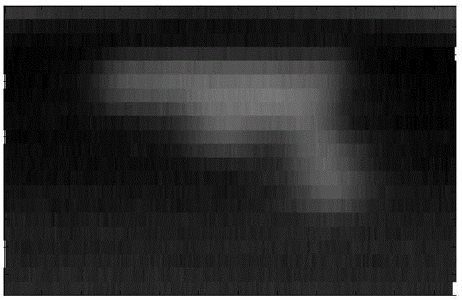
[0022] Step 1. According to the passive ranging model, two passive millimeter-wave radiation imaging systems with the same parameter settings are placed on a straight line with respect to the target scene, and the same target scene is imaged by the two passive millimeter-wave radiation imaging systems. The corresponding measurement imaging data, the imaging results are shown in Figure 3(a) and Figure 3(b); specifically:

[0023] Passive ranging models such as figure 2 As shown, let f be the focal length of the passive millimeter-wave radiation imaging system, d 1 is the distance between the two imaging systems before and after, d is the distance between the target and the first imaging system, then the distance between the target and the second imaging system is d+d 1 ; Assume that the a...


PUM


Abstract

The present invention discloses an image processing technology-based passive millimeter wave radiation imaging system distance measurement method. The method includes the following steps that: two sets of passive millimeter wave radiation imaging systems of which the parameter settings are consistent are arranged on the same straight line sequentially relative to a target scene according to a passive distance measurement model; the same target scene is imaged through the two sets of passive millimeter wave radiation imaging systems, so that corresponding measurement imaging data are obtained; three characteristic points with the highest target scene matching degree are extracted from two groups of measurement imaging data through using a surf matching algorithm; and the area of connected regions of the characteristic points is calculated, and a target distance can be calculated through the passive distance measurement model. According to the distance measurement method of the invention, the passive millimeter wave radiometers are adopted to carry out imaging, and therefore, compared with photoelectric and infrared passive distance measurement methods, the distance measurement method of the invention can obtain better imaging results and higher distance measurement accuracy in harsh environments such as cloud, fog, battlefield smoke and so on.

Description

technical field [0001] The invention belongs to passive ranging technology, in particular to a passive millimeter wave radiation imaging system ranging method based on image processing technology. Background technique [0002] Objects whose physical temperature is higher than absolute zero will radiate electromagnetic waves outward. When the object is irradiated by external electromagnetic waves, it will also produce reflection, scattering, transmission and absorption phenomena. Objects with different material structures have differences in their radiation, scattering and reflection of electromagnetic waves. The millimeter-wave passive imaging system is to distinguish different objects according to the difference in target radiation brightness and temperature, and then achieve the purpose of imaging the observation scene. Compared with infrared imaging systems, passive millimeter-wave radiation imaging systems have the ability to penetrate smoke and work in harsh environmen...

Claims


Application Information

Patent Timeline
IPC IPC(8): G01S11/12
CPCG01S11/12
Inventor 吴礼王强李冬周仁峰李勇强
Owner NANJING UNIV OF SCI & TECH
Learn More