Deformation and slope synchronous measurement device and method based on digital speckle interferometry

A digital speckle and synchronous measurement technology, which is applied in the field of optical measurement, can solve the problems of complex optical path system, non-independence, and low measurement accuracy, and achieve the effect of simple overall system structure, adjustable measurement sensitivity, and reduced complexity

Active Publication Date: 2017-02-15
YANCHENG INST OF TECH
View PDF8 Cites 18 Cited by
  • Summary
  • Abstract
  • Description
  • Claims
  • Application Information

AI Technical Summary

Problems solved by technology

[0003] At present, the simultaneous measurement methods of object deformation and slope based on digital speckle interferometry are mainly divided into three categories: the first category is multi-aperture shearing digital speckle interferometry, which needs to make special multi-aperture templates for different test objects. The system is relatively complex, and the obtained deformation and slope information are coupled with each other and are not independent; the second type is Michelson shearing digital speckle interferometry technology, the carrier frequency deformation information and slope information obtained by this technology are coupled with each other and are not independent , it is necessary to set a suitable frequency ...

Method used


Image

  • Deformation and slope synchronous measurement device and method based on digital speckle interferometry
  • Deformation and slope synchronous measurement device and method based on digital speckle interferometry
  • Deformation and slope synchronous measurement device and method based on digital speckle interferometry

Examples


Embodiment

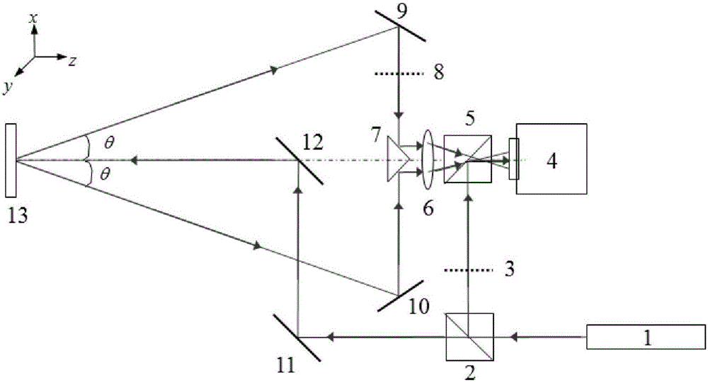
[0029] Embodiment: A deformation and slope simultaneous measurement device based on digital speckle interference, such as figure 1 As shown, it includes a laser transmitter 1, a first dichroic prism 2, a first optical switch 3, a monochromatic CCD camera 4, a second dichroic prism 5, an imaging lens 6, a side all-inverted rectangular prism 7, a second optical switch 8, A first plane mirror 9 , a second plane mirror 10 , a third plane mirror 11 , a fourth plane mirror 12 and a measured object 13 .

[0030] The laser emitter 1 emits laser light along the horizontal direction, and after passing through the first dichroic prism 2 on the left side of the laser emitter 1, it is divided into reflected light and transmitted light, thus forming a reference optical path and an object optical path.

[0031] The object optical path is that the separated transmitted light is reflected to the surface of the measured object 13 through the third plane mirror 11 and the fourth plane mirror 12,...


PUM


Abstract

The invention discloses a deformation and slope synchronous measurement device and method based on digital speckle interferometry. Light from a laser is divided into a first beam of light and a second beam of light by a beam splitter prism. The first beam of light is reflected onto an imaging target surface of a monochrome CCD camera by another beam splitter prism, thereby forming a reference optical path. The second beam of light is reflected to a surface of a measured object via a plane mirror, thereby forming a laser speckle field. The monochrome CCD camera receives the laser speckle field at the same time from two directions which are symmetric to an optical axis, so that two object optical paths are formed. By switching the on/off state of the reference optical path and the object optical path, a digital speckle interference optical path and a shear digital speckle interference optical path for synchronous measurement are formed, a speckle interference fringe phase and a shear speckle interference fringe phase are extracted, and the surface deformation and slope of the measured object are measured. The invention realizes synchronous and independent measurement of deformation and slope information of the measured object, without repeated loading and later separation. The phase shift technology is adopted, thereby improving the measurement accuracy. The dual speckle interference optical paths with adjustable measurement sensitivity and object-light sharing are constructed, so the whole structure of the system is simple and compact.

Description

technical field [0001] The invention relates to the technical field of optical measurement, in particular to a digital speckle interferometry method. Background technique [0002] Digital speckle interferometry and shearing digital speckle interferometry are two full-field, non-contact, high-precision, high-sensitivity optical measurement techniques based on laser speckle interferometry. The former is widely used in deformation measurement, vibration analysis, shape testing and defect detection on the surface of objects, while the latter can directly measure the slope of object deformation and is mainly used in the field of industrial non-destructive testing. Integrating digital speckle interferometry and shearing digital speckle interferometry to carry out simultaneous measurement research on object deformation and slope information is more convenient for solving the problem of non-destructive testing of internal defects in objects with relatively large deformation and rela...

Claims


Application Information

Patent Timeline
IPC IPC(8): G01B11/16G01B11/26
CPCG01B11/162G01B11/26Y02A10/23
Inventor 顾国庆佘斌孔海陵王路珍
Owner YANCHENG INST OF TECH
Why Eureka
Try Eureka