
Confining pressure cavity hydraulic oil recovery device

A technology of recovery device and hydraulic oil, applied in the direction of fluid pressure actuating device, fluid pressure actuating system components, mechanical equipment, etc. The effect of protecting the laboratory environment, saving hydraulic oil, and high safety

Inactive Publication Date: 2017-02-15
HUBEI POLYTECHNIC INST
View PDF5 Cites 1 Cited by
  • Summary
  • Abstract
  • Description
  • Claims
  • Application Information

AI Technical Summary

Problems solved by technology

However, in the confining pressure chamber of the indoor triaxial test system (applied confining pressure, σ 2 and σ 3 ) oil leakage often occurs, resulting in test waste and indoor equipment pollution. In order to solve the problem of hydraulic oil recovery, it is thought of installing a hydraulic oil recovery device on the base of the confining pressure chamber.
[0005] At present, the confining pressure chamber (oil pressure chamber) of most indoor triaxial test systems has the problems of hydraulic oil leakage and endless flowback, and it is difficult to recover the leaked and non-flowback hydraulic oil

Method used


Image

  • Confining pressure cavity hydraulic oil recovery device
  • Confining pressure cavity hydraulic oil recovery device
  • Confining pressure cavity hydraulic oil recovery device

Examples


Embodiment Construction

[0029] In order to have a clearer understanding of the technical features, purposes and effects of the present invention, the specific implementation manners of the present invention will now be described in detail with reference to the accompanying drawings.

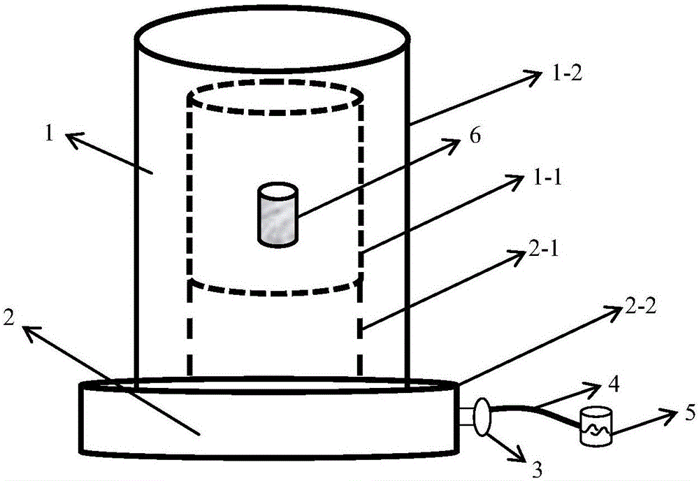
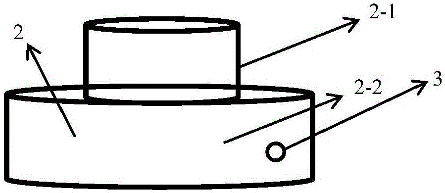
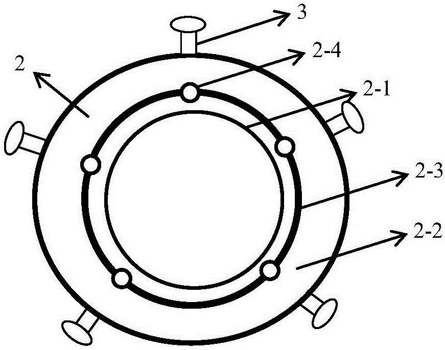
[0030] according to figure 1 , Figure 2a , Figure 2b , image 3 It can be seen that a hydraulic oil recovery device for an oil pressure chamber includes: an oil pressure chamber cylinder 1 , an oil pressure chamber base 2 , a hydraulic oil recovery control valve 3 , a hydraulic oil recovery pipe 4 , and a hydraulic oil recovery barrel 5 . It is characterized in that: the inner wall 1-1 of the oil pressure chamber is connected with the upper cylinder 2-1 of the base of the oil pressure chamber, and the seamless connection is realized under the test conditions, and the hydraulic oil recovery control valve 3 is installed under the base of the oil pressure chamber On the side of the cylinder 2-2, one end of the hydraul...


PUM


Abstract

The invention relates to a confining pressure cavity hydraulic oil recovery device which comprises an oil pressure cavity barrel, an oil pressure cavity base, a hydraulic oil recovering control valve, a hydraulic oil recovering pipe and a hydraulic oil recovering barrel; the oil pressure cavity barrel is a thick-wall cylinder with an opening in the lower end, and comprises an oil pressure cavity barrel inner wall and an oil pressure cavity barrel outer wall; the oil pressure cavity base comprises an upper cylinder body of the base and a lower cylinder body of the base, a hydraulic oil recovering hole is formed in the surface of the lower cylinder body of the base, and meanwhile a hydraulic oil recovering channel is formed in the base; and the hydraulic oil recovering barrel is communicated with the hydraulic oil recovering channel through the hydraulic oil recovering hole, a recovering control valve and the hydraulic oil recovering pipe. A complete recovering device is formed by the recovering channel, the recovering hole, the recovering control valve, the recovering pipe and the recovering barrel, and the confining pressure cavity hydraulic oil recovery device is suitable for liquid recovering and reusing, and is particularly suitable for indoor test liquid recovering. The confining pressure cavity hydraulic oil recovery device has a certain application prospect on tri-axial tests of on-site rock mass samples in the field of ground, tunnels, bridges, metros and the like.

Description

technical field [0001] The invention relates to the field of research on mechanical properties of rock and soil, and more specifically relates to a hydraulic oil recovery device for a confining pressure chamber. Background technique [0002] According to the principle of mechanics, any object is subjected to forces from three directions of X, Y, and Z, which are called the maximum principal stress, the middle principal stress and the minimum principal stress respectively, and are denoted by the symbol σ 1 , σ 2 , σ 3 express. In the conventional geotechnical environment, the rock and soil mass is actually in a state of plane strain. To test the mechanical properties of forces in these geotechnical environments, it is often treated as an axisymmetric problem, that is, σ 2 = σ 3 . The conventional triaxial test is to test the sample under axisymmetric stress state. [0003] The indoor triaxial test system studies the relationship between principal stress and strain and s...

Claims


Application Information

Patent Timeline
Patent Type & Authority Applications(China)
IPC IPC(8): F15B21/04F15B21/14
CPCF15B21/04F15B21/14
Inventor 袁晓洲熊世明
Owner HUBEI POLYTECHNIC INST
Learn More