
Composite floor base material

A composite floor and substrate technology, applied in the direction of floor covering, application, home appliances, etc., can solve the problems of human health and safety hazards, insufficient connection between layers, excessive content of harmful substances, etc., to avoid warping and cracking , the effect of reducing gaps and reducing internal stress

Active Publication Date: 2017-02-15
史广福
View PDF5 Cites 3 Cited by
  • Summary
  • Abstract
  • Description
  • Claims
  • Application Information

AI Technical Summary

Problems solved by technology

[0003] The existing composite floor substrates have the following defects: high cost; easy to deform; complicated preparation process; insufficient connection between layers and prone to warping and cracking
Even some composite floorings contain formaldehyde and other harmful substances exceeding the standard, and because of the poor internal air permeability, formaldehyde and other substances are not easy to discharge, which poses serious health and safety risks to the human body, is not environmentally friendly, and cannot be widely promoted in the market

Method used


Image

  • Composite floor base material
  • Composite floor base material
  • Composite floor base material

Examples


Embodiment Construction

[0030] The present invention will be described in further detail below in conjunction with the accompanying drawings and embodiments, so that those skilled in the art can implement it with reference to the description.

[0031] It should be understood that terms such as "having", "comprising" and "including" as used herein do not entail the presence or addition of one or more other elements or combinations thereof.

[0032] It should be noted that the experimental methods described in the following embodiments, unless otherwise specified, are conventional methods, and the reagents and materials, unless otherwise specified, can be obtained from commercial sources.

[0033]In the description of the present invention, the terms "transverse", "longitudinal", "upper", "lower", "front", "rear", "left", "right", "vertical", "horizontal", " The orientations or positional relationships indicated by "top", "bottom", "inner", "outer", etc. are based on the orientations or positional rela...


PUM

PropertyMeasurementUnit
Particle sizeaaaaaaaaaa

Abstract

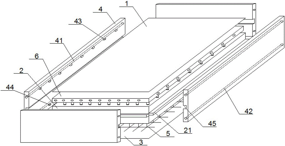
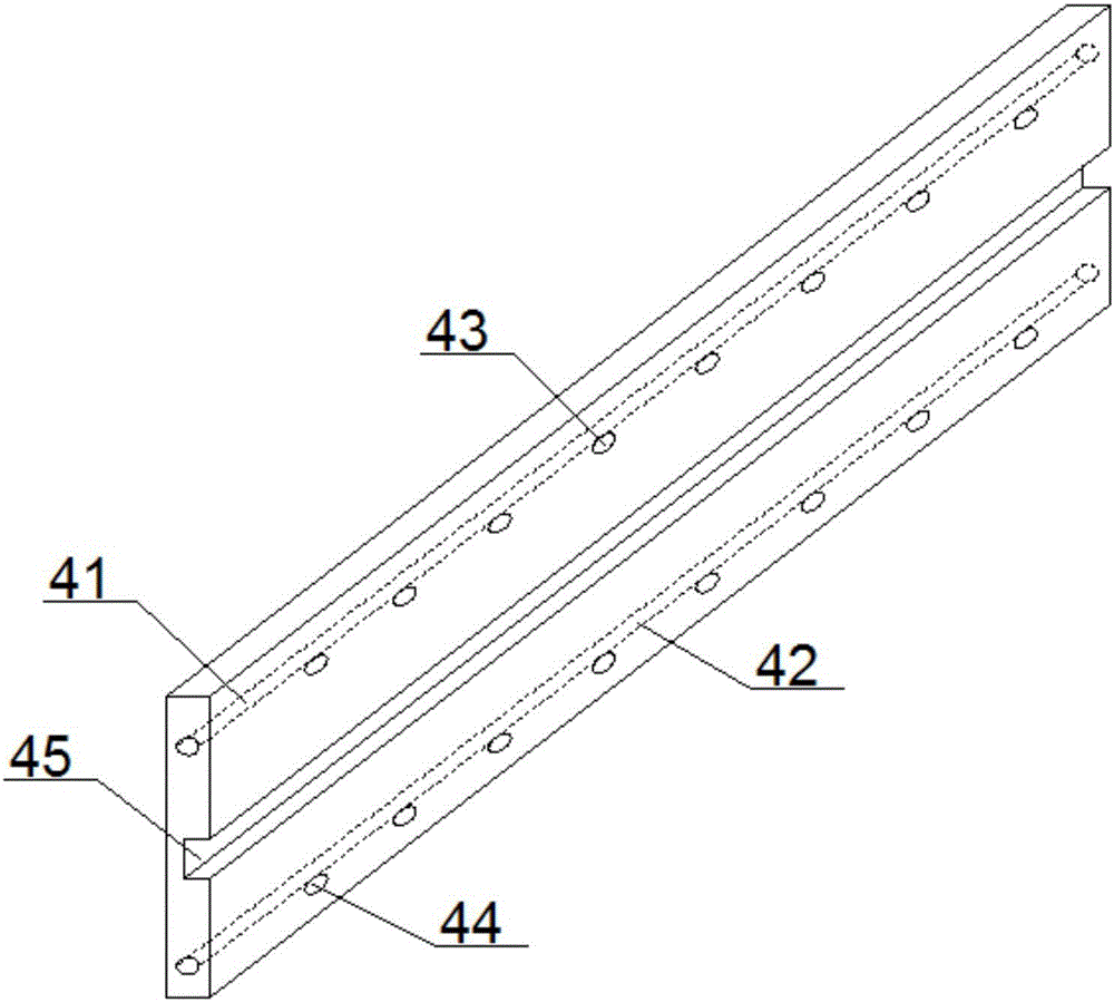
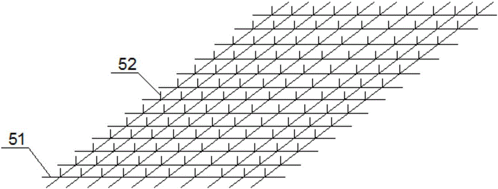
The invention discloses a composite floor base material which comprises a bottom plate, a surface plate, a core plate located between the bottom plate and the surface plate, and four side plates. A fiber web is laid between the bottom plate and the core plate. A thin plate is laid between the core plate and the surface plate. A plurality of first hollow slim tubes extending upwards in the vertical direction are arranged on the fiber web, and the two ends of the first slim tubes are open. A plurality of first through holes and a plurality of second through holes are formed in the thin plate. Second slim tubes extending downwards in the vertical direction are arranged on the lower surface of the thin plate. The upper ends of the second slim tubes stretch into the thin plate and communicate with the first through holes and the second through holes. Third through holes and fourth through holes are formed in the side plates. First round grooves and second round grooves are formed in one side face of each side plate. The first slim tubes and the second slim tubes communicate with the third through holes and the fourth through holes correspondingly, and thus air ventilation paths are formed. The composite floor base material is simple in production technique, good in ventilation property and air permeability and worthy of wide popularization on the market and has the advantage of being environmentally friendly.

Description

technical field [0001] The invention relates to the field of composite floors. More specifically, the present invention relates to a composite flooring substrate. Background technique [0002] Laminate flooring is usually laid on the ground as the surface structure of the ground, and is mainly used to decorate the ground to bring aesthetic feeling to people. As the core part of composite flooring, the base material is the focus of research and improvement by researchers in this field. Only by ensuring the quality and environmental performance of the composite floor base material can the safety and reliability of the composite floor be guaranteed. [0003] The existing composite floor base material has the following defects: high cost; easy deformation; complicated preparation process; insufficient connection between layers and easy warping and cracking. Even some composite floorings contain excessive formaldehyde and other harmful substances, and because of their poor inte...

Claims


Application Information

Patent Timeline
IPC IPC(8): E04F15/02B32B3/06B32B3/08B32B3/26B32B5/02B32B21/02B32B21/10
CPCB32B3/06B32B3/08B32B3/26B32B5/028B32B21/02B32B21/10B32B2262/067B32B2264/102B32B2264/108B32B2264/12B32B2307/54B32B2307/72B32B2307/724B32B2471/00E04F15/02
Inventor 彭展忠
Owner 史广福
Learn More