Optical fiber perform rod casing tube sintering device, and sintering method thereof
A technology of optical fiber preform and sintering device, which is applied in the direction of manufacturing tools, glass manufacturing equipment, glass production, etc., and can solve the problems of increasing the complexity of the equipment, the space occupied by the equipment, increasing the manufacturing cost of the optical fiber preform, and the expensive helium consumption and other issues, to achieve the effect of facilitating large-scale mass production, reducing equipment complexity, and reducing production costs
- Summary
- Abstract
- Description
- Claims
- Application Information
AI Technical Summary
Problems solved by technology
Method used
Image
Examples
Embodiment 1
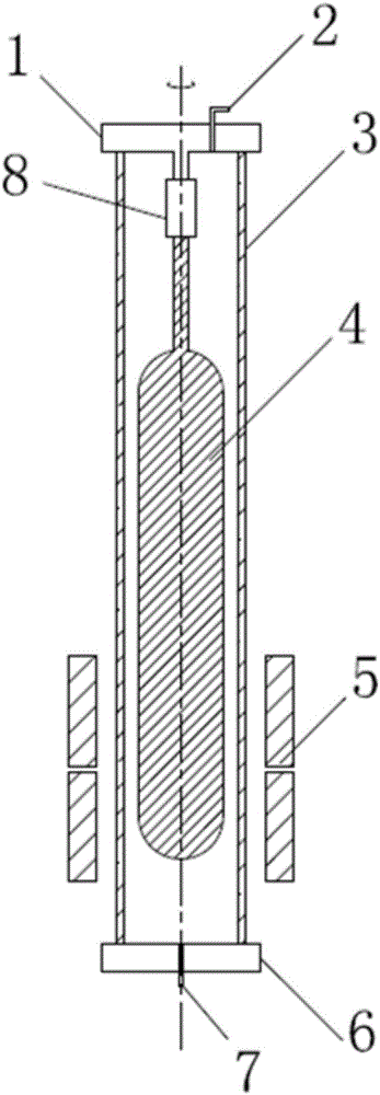
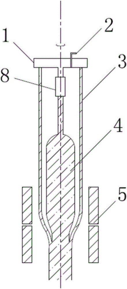
[0044] like Figure 1 to Figure 2 As shown, it is an optical fiber preform casing sintering device according to this embodiment, which includes a casing 3, an upper fixing device 1, a lower fixing device 6, and a heating furnace 5, wherein the casing 3 passes through the upper fixing device 1 and the lower fixing device 6 are vertically installed in the heating furnace 5, an optical fiber preform loose body 4 is arranged in the sleeve 3 and connected with the upper fixing device 1; the upper fixing The device 1 is provided with an exhaust mechanism 2 which is connected with the exhaust system and the vacuum pump through a valve switch, and the lower fixing device 6 is provided with an air intake mechanism 7 .
[0045] Preferably, the upper fixing device 1 and the lower fixing device 6 are driven by a rotating mechanism, and both can rotate synchronously.
[0046] Preferably, the fiber preform loose body 4 is connected to the upper fixing device 1 through a connection mechanism ...
Embodiment 2
[0051] The sintering method based on the optical fiber preform casing sintering device described in Embodiment 1 comprises the following steps:
[0052] S1: installing the casing 3 in the heating furnace 5 in a vertical manner through the upper fixing device 1 and the lower fixing device 6;
[0053] S2: setting the loose body 4 of the optical fiber preform in the casing 3 and connecting it with the upper fixing device 1;
[0054] S3: removing the hydroxyl groups introduced by the production process in the loose body 4 of the optical fiber preform by heating and moving the heating furnace 5;
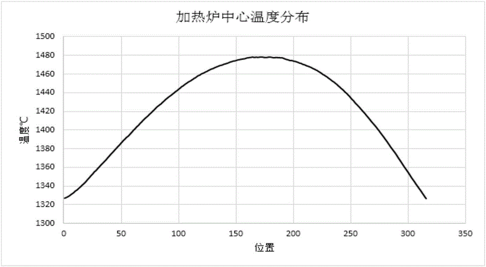
[0055] S4: Move the heating furnace 5 to the bottom of the fiber preform loose body 4, raise the temperature to above 1450°C, and form a temperature gradient distribution, the temperature distribution is as follows image 3 shown;
[0056] S5: under the sintering temperature condition of 1450°C to 1550°C, the lower end part of the loose body 4 of the optical fiber preform is vitrified; ...
PUM
 Abstract
Description
Claims
Application Information
 - R&D Engineer
- R&D Manager
- IP Professional
- Industry Leading Data Capabilities
- Powerful AI technology
- Patent DNA Extraction
Browse by: Latest US Patents, China's latest patents, Technical Efficacy Thesaurus, Application Domain, Technology Topic, Popular Technical Reports.
© 2024 PatSnap. All rights reserved.Legal|Privacy policy|Modern Slavery Act Transparency Statement|Sitemap|About US| Contact US: help@patsnap.com


