
Safety braking mechanism

A technology of safety brake and brake pin, which is applied in the direction of clockwork mechanism and hoisting device, etc., can solve the problems of equipment lack of safety brake mechanism or brake mechanism, imperfection, etc., achieve simple structure and prevent safety problems , The effect of convenient maintenance

Active Publication Date: 2017-02-15
DALIAN AIWOTE ROBOT TECH CO LTD
View PDF7 Cites 1 Cited by
  • Summary
  • Abstract
  • Description
  • Claims
  • Application Information

AI Technical Summary

Problems solved by technology

[0004] The invention mainly solves the safety problems that the equipment in the prior art lacks or the braking mechanism is not perfect, and the equipment is easy to occur during the operation and maintenance process, and provides a safety braking mechanism to improve the safety of equipment operation and maintenance sex

Method used


Image

  • Safety braking mechanism
  • Safety braking mechanism

Examples


Embodiment Construction

[0023] In order to make the technical problems solved by the present invention, the technical solutions adopted and the technical effects achieved clearer, the present invention will be further described in detail below in conjunction with the accompanying drawings and embodiments. It should be understood that the specific embodiments described here are only used to explain the present invention, but not to limit the present invention. In addition, it should be noted that, for the convenience of description, only parts related to the present invention are shown in the drawings but not all content.

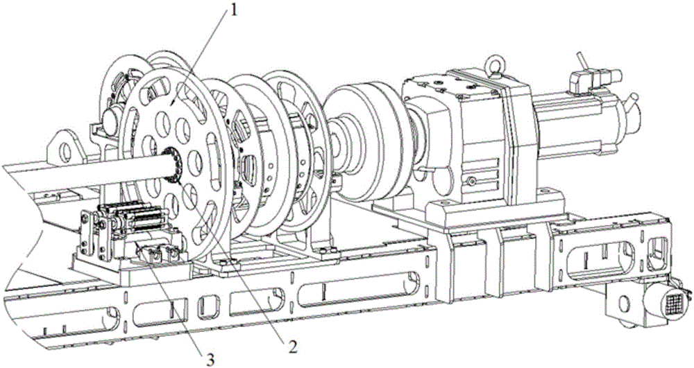
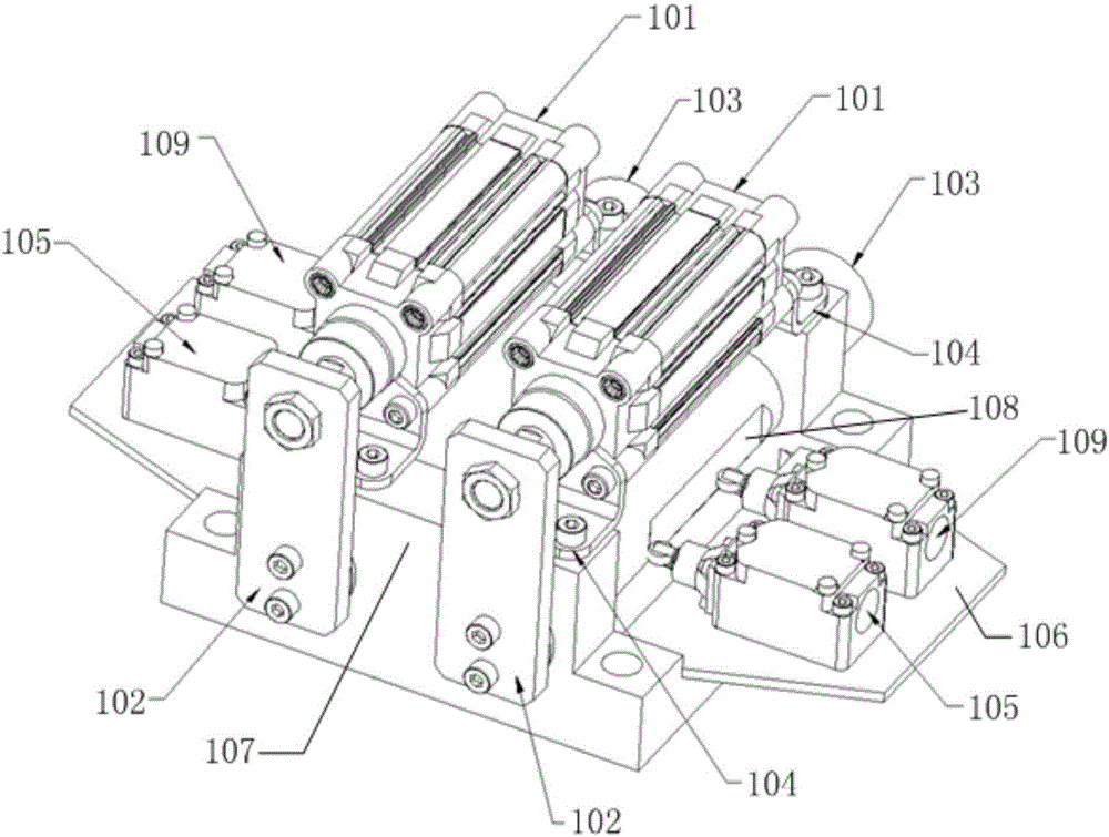
[0024] figure 1 It is a schematic diagram of the application structure of the safety braking mechanism provided by the present invention. like figure 1 As shown, the safety brake mechanism provided by the embodiment of the present invention includes: a brake wheel 1 , an installation base 106 and two brake units 3 symmetrically arranged on both sides of the center line of the ins...


PUM


Abstract

The invention relates to the field of body-in-white conveying equipment, and provides a safety braking mechanism. The safety braking mechanism comprises a braking wheel, a mounting base and two braking units symmetrically arranged on the two sides of the middle line of the mounting base. The braking wheel and the mounting base are mounted on an upper frame body of the conveying equipment. Bosses are arranged at the two ends of the mounting base correspondingly. Each braking unit comprises an air cylinder, a connecting plate and a braking pin. The two ends of a cylinder body of each air cylinder are fixed to the bosses at the two ends of the mounting base correspondingly, and a piston rod of each air cylinder is connected with one end of the corresponding connecting plate. The end, connected with the corresponding piston rod, of the tail of each connecting plate is connected with one end of the corresponding braking pin. Each braking pin penetrates the bosses at the two ends of the mounting base and is parallel to the corresponding air cylinder, and the length of each braking pin is larger than that of the mounting base. Arc-shaped holes used for being matched with the braking pins are evenly distributed in the braking wheel in the circumferential direction. According to the safety braking mechanism, the equipment can be stopped working during power interruption and air interruption, and the safety of the equipment during operating and maintaining is improved.

Description

technical field [0001] The invention relates to the field of body-in-white conveying equipment, in particular to a safety braking mechanism. Background technique [0002] In the body-in-white conveying equipment of the production line, the upper frame lifts the body-in-white through motors, belts, etc., so that the equipment rises to the right position, and the conveying equipment moves horizontally to the next station. During the transportation process, if the equipment is abnormal, there may be sudden gas failure, power failure or sudden fall of the lower frame, etc. At this time, it is necessary to brake the equipment to prevent production safety problems. In addition, during equipment maintenance, if the equipment does not stop accurately, it may cause injury to workers. [0003] At present, the body-in-white conveying equipment lacks a safety braking mechanism or the braking mechanism is not perfect, which leads to safety problems, affects the work efficiency of automo...

Claims


Application Information

Patent Timeline
Patent Type & Authority Applications(China)
IPC IPC(8): B66D1/54
CPCB66D1/54
Inventor 何田飞
Owner DALIAN AIWOTE ROBOT TECH CO LTD
Learn More