
A Angular Momentum Unloading Method for Electric Propulsion Considering Thruster Arc Loss

A technology of angular momentum unloading and thrusters, which is applied in the direction of aerospace vehicle propulsion system devices, aerospace vehicle guidance devices, etc., and can solve problems such as limited arrangement of electric thrusters, reduced unloading accuracy, and inability to form force couples

Active Publication Date: 2019-05-24
BEIJING INST OF CONTROL ENG
View PDF5 Cites 0 Cited by
  • Summary
  • Abstract
  • Description
  • Claims
  • Application Information

AI Technical Summary

Problems solved by technology

[0003] The existing electric thruster unloading is based on the traditional chemical propulsion system. When it is applied to the electric propulsion control, it has the following disadvantages: ①Chemical propulsion can use two thrusters to form a couple, and perform angular momentum unloading alone. The layout on the star is limited, and it is impossible to form a force couple, so it needs to be unloaded while controlling the orbit; ②The unloading of the chemical thruster used for position maintenance is more flexible and can be carried out at any time. A few days to more than ten days is the cycle control, and the ignition is regular several times a day; ③The thrust of the chemical thruster is several N-tens of N, and the control force can be regarded as the form of pulse, while the thrust of the electric thruster is only for 10 -2 ~10 -1 N, when the combined orbit control ignition time is too long, the control force is regarded as a pulse form, which will reduce the unloading accuracy

Method used


Image

  • A Angular Momentum Unloading Method for Electric Propulsion Considering Thruster Arc Loss
  • A Angular Momentum Unloading Method for Electric Propulsion Considering Thruster Arc Loss
  • A Angular Momentum Unloading Method for Electric Propulsion Considering Thruster Arc Loss

Examples


Embodiment

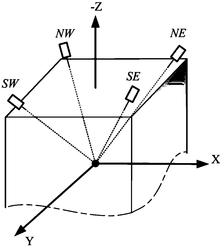
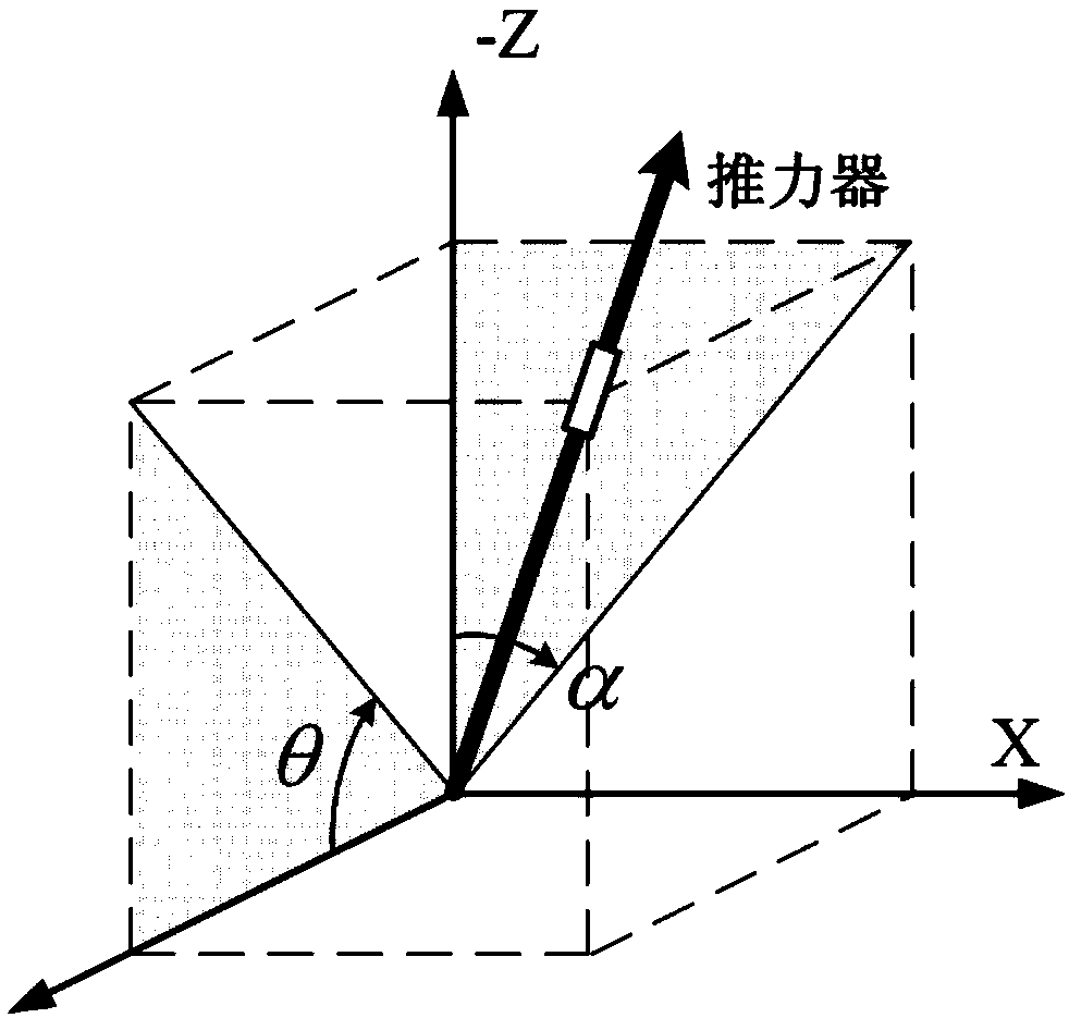
[0155] An electric propulsion angular momentum unloading method considering the loss of the arc section of the thruster is disclosed. The method is suitable for the layout of the conical electric thruster, and four electric thrusters are symmetrically installed in pairs and obliquely on the four sides of the upper back floor of the satellite. Two electric thrusters on each diagonal form a pair, a total of two pairs of electric thrusters. α is the angle between the projection of the thrust direction vector of the electric thruster installed in the northwest (NW) on the x-z plane of the satellite itself and the z-axis, and θ is the thrust direction vector of the electric thruster installed in the northwest (NW) direction in the satellite itself. The angle between the y-z plane projection of the system and the y-axis. This method is calculated at the beginning of a period of variation of the vector adjustment mechanism of an electric thruster, and the steps are as follows:

[01...


PUM


Abstract

The invention discloses an electric propulsion angular momentum unloading method taking thruster arc section losses into consideration. The method is suitable for earth synchronous orbit electric propulsion satellites conically arranged, a vector adjusting mechanism adjusting electric thrusters is used for generating the moment of momentum, and angular momentum unloading of an on-satellite angular momentum exchange executing mechanism is achieved. Firstly, under the situation that any unloading number of days is given, and ignition combinations (a normal or fault mode) are kept at any positions of the electric thrusters on the diagonal line, a common and simplified electric propulsion angular momentum unloading dynamics model taking the arc section losses into consideration is established; then, method establishing conditions and an electric thruster deflection angle obtaining method are given; and finally, a treatment manner under the situation of the overload of angular momentum unloading is given. According to the method, through proper simplification on the dynamics model, the calculated amount of the unloading method is reduced, the arc section losses of electric thruster ignition are taken into consideration, the angular momentum unloading precision is improved, and an effective method is provided for in-orbit angular momentum unloading of the electric thrusters.

Description

technical field [0001] The invention relates to an electric propulsion angular momentum unloading method considering the arc section loss of the thruster, which is mainly used on the geosynchronous orbit electric propulsion satellite with a conical layout, and is used for the electric propulsion angular momentum unloading of the angular momentum exchange actuator on the star . Background technique [0002] Electric propulsion is the development trend of communication satellites and deep space probes in recent years, which can significantly reduce fuel consumption during space missions and improve the life of spacecraft. For orbiting satellites, the installation configuration of electric thrusters often adopts a conical layout, and four electric thrusters are installed in pairs and symmetrically on the four sides of the back floor of the satellite. Under this thruster layout, the electric propulsion angular momentum unloading needs to be carried out simultaneously with the o...

Claims


Application Information

Patent Timeline
IPC IPC(8): B64G1/24B64G1/40
CPCB64G1/24B64G1/40
Inventor 马雪石恒胡少春陈守磊韩冬汤亮刘潇翔
Owner BEIJING INST OF CONTROL ENG
Learn More