Feeder assembly equipment and assembly method thereof

A technology for assembling equipment and feeders, which is applied in metal processing equipment, metal processing, manufacturing tools, etc., can solve the problems of unstable quality, difficult process guarantee, low production capacity, etc., and achieve simple and excellent process, fast assembly speed, The effect of stable quality

Active Publication Date: 2018-11-13
COMBA TELECOM TECH (GUANGZHOU) CO LTD +2
View PDF7 Cites 0 Cited by
  • Summary
  • Abstract
  • Description
  • Claims
  • Application Information

AI Technical Summary

Problems solved by technology

In the prior art of producing and assembling feeders, the production steps are as follows: firstly assemble the socket member 721 and the first support member 722 to form the socket assembly 72, and assemble the pin member 731 and the second support member 732 on the Form the pin assembly 73 together, and then put the socket assembly 72 and the pin assembly 73 into the housing 71 through a clamp, and then use a manual press to press the parts together, and the medium sleeve 74 is easy to be crushed during assembly. As a result, the function of the feeder 7 is lost, so it can only be repaired and reassembled, and parts such as the socket part 721, the first support part 722, the pin part 731, the second support part 732 and the dielectric sleeve 74 are easily scrapped during the repair. Seriously, the shell 71 will be scratched and the shell 71 will be scrapped, resulting in low production capacity, unstable quality, high anti-repair rate, serious waste, inconvenient operation, high labor intensity, high risk, and difficult to guarantee the process
[0004] Therefore, how to solve the problems of low production capacity, unstable quality, high anti-repair rate, and serious waste in the assembly of power feeders is a major topic explored by technicians in the industry.

Method used


Image

  • Feeder assembly equipment and assembly method thereof
  • Feeder assembly equipment and assembly method thereof
  • Feeder assembly equipment and assembly method thereof

Examples


Embodiment Construction

[0037] In order to enable those skilled in the art to better understand the solutions of the present invention, the following will clearly and completely describe the technical solutions in the embodiments of the present invention in conjunction with the drawings in the embodiments of the present invention. Obviously, the described embodiments are only It is a part of embodiments of the present invention, but not all embodiments. Based on the embodiments of the present invention, all other embodiments obtained by those skilled in the art without creative efforts fall within the protection scope of the present invention.

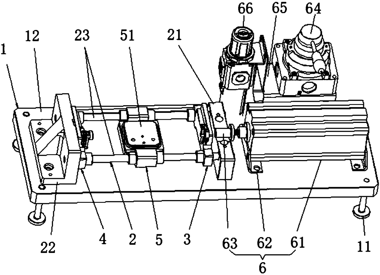
[0038] The present invention provides a feeder assembly equipment, please refer to image 3 with Figure 8 , the assembly equipment includes: a frame 1, a supporting mechanism 2, a first locking mechanism 3, a second locking mechanism 4, a sliding mechanism 5 and a pushing assembly (in this embodiment, a pneumatic device 6).

[0039] Please refer to image 3...


PUM


Abstract

The invention discloses assembling equipment for a power feeding device. The assembling equipment comprises a support mechanism, a first locking mechanism, a second locking mechanism, a sliding mechanism and a pushing assembly, wherein the support mechanism is provided with a second pressing head and a sliding rail; one of the first locking mechanism and the second locking mechanism is used for locking a jack assembly, the other is used for locking a pin assembly, and the sliding mechanism is used for fixing a shell of the power feeding device; the first locking mechanism, the sliding mechanism and the second locking mechanism are sequentially arranged on the sliding rail in a slidable sleeving manner; the pushing assembly comprises a driving mechanism and a first pressing head, one of the first pressing head and the second pressing head is used for pressing the pin assembly, and the other is used for pressing the jack assembly; and the first pressing head, driven by the driving mechanism, can push the pin assembly or the jack assembly which is pressed by the first pressing head to move and plug the pin assembly into the jack assembly. Through the assembling equipment, the pin assembly and the jack assembly of the power feeding device can be accurately assembled into the shell, the operation is simple, and the quality of the power feeding device is stable and reliable.

Description

technical field [0001] The invention relates to the field of mobile communication radio frequency manufacturing and processing, in particular to assembly equipment and an assembly method for feeders in production assembly. Background technique [0002] In order to improve the sensitivity and signal coverage of mobile communication base stations, tower-mounted amplifier subsystems are widely used at present. The subsystem is composed of duplex tower top amplifier, feeder, lightning arrester, power monitoring unit and so on. Among them, feeders (such as figure 1 ) is to feed direct current (DC) into the cable and then to the tower top amplifier to power the low noise amplifier. [0003] Please refer to figure 1 with figure 2 , the feeder 7 includes a housing 71 , a jack assembly 72 , a pin assembly 73 and a dielectric sleeve 74 . The housing 71 is provided with a retaining spring 711, a sealing ring 712 and a threaded sleeve 713; the jack assembly 72 includes a jack memb...

Claims


Application Information

Patent Timeline
Patent Type & Authority Patents(China)
IPC IPC(8): B23P19/027
CPCB23P19/006B23P19/027
Inventor 黄武朱龙翔徐华谢维陈永榆
Owner COMBA TELECOM TECH (GUANGZHOU) CO LTD
Why Eureka
Try Eureka