
A spiral vane diversion type phase separation device

A technology of spiral flow diversion and phase separation, which is applied in the direction of swirl devices and devices whose axial direction of swirl can be reversed, etc. It can solve the problems that light phase fluids cannot be merged and cannot make full use of the circumferentially distributed rotation generating units, etc. , to achieve the effect of light weight, good industrial application prospect and high separation efficiency

Active Publication Date: 2019-08-09
INST OF MECHANICS CHINESE ACAD OF SCI +1
View PDF8 Cites 0 Cited by
  • Summary
  • Abstract
  • Description
  • Claims
  • Application Information

AI Technical Summary

Problems solved by technology

[0004] However, the current separators designed according to the centrifugal principle generally ignore a problem. The two-phase mixed fluid tends to form a stratified flow during the process of transporting to the phase separation device, so that the circumferentially distributed rotation generating units cannot be fully utilized to make the light phase Fluid cannot coalesce quickly and efficiently into the central area of ​​the separator

Method used


Image

  • A spiral vane diversion type phase separation device
  • A spiral vane diversion type phase separation device
  • A spiral vane diversion type phase separation device

Examples


Embodiment Construction

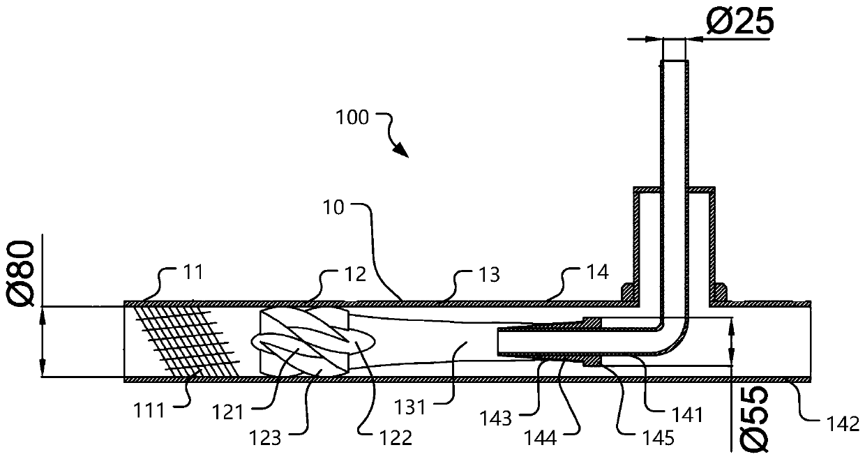
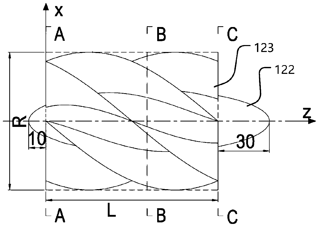
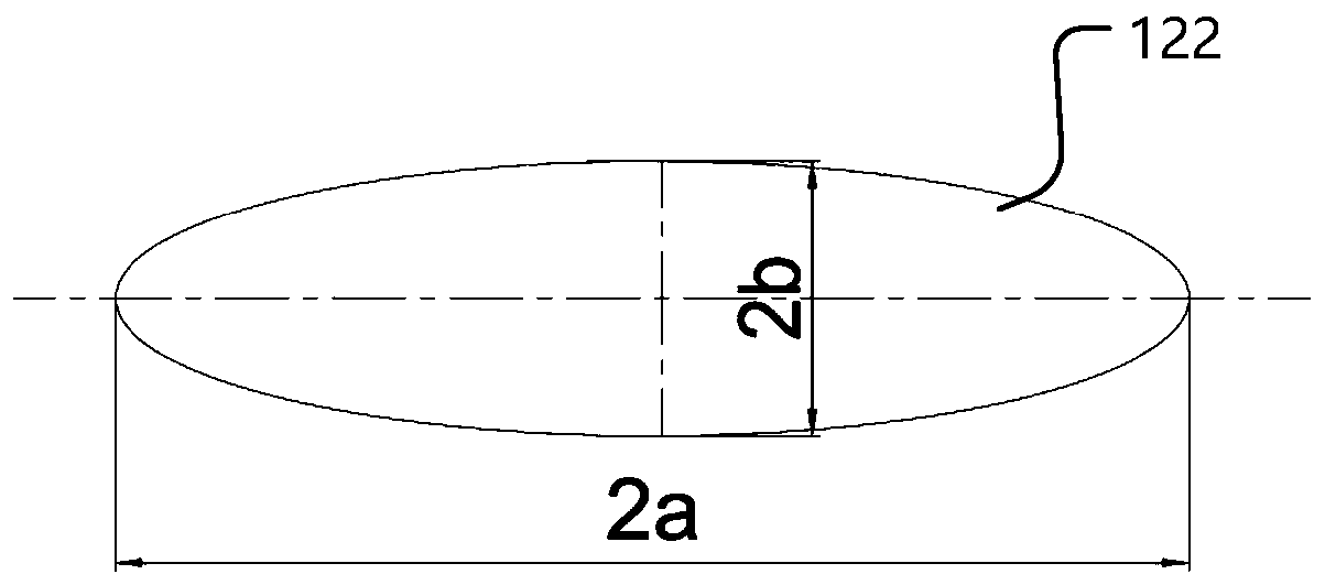
[0028] Such as figure 1 , 2 , 3, the spiral vane flow guide type phase separation device 100 of an embodiment of the present invention generally includes a separation pipe 10 for providing an installation basis for each component, and the separation pipe is based on the separation of the mixed liquid. The function is divided into mixing section 11, swirl section 12, separation section 13 and discharge section 14 in turn.

[0029] The blending section 11 is connected to the input pipe of the liquid to be separated, and a static mixer 111 is arranged inside, and the static mixer 111 is used to fully mix the input liquid, and the mixing includes multiple divisions, shifting and remixing, etc. The process makes the incoming mixed liquids that have already appeared stratification completely mixed together, providing guarantee for the subsequent cyclone separation. The static mixer 111 can make the incoming liquid mix regularly and repeatedly under the three mixing elements of "di...


PUM


Abstract

The invention provides a spiral piece flow guiding type phase separation device. The spiral piece flow guiding type phase separation device comprises a separation tube. The separation tube is sequentially divided into a mixing section, a swirl section, a separation section and a discharging section according to effect regions, wherein the mixing section is internally provided with a static mixer which is used for fully mixing input liquid; a swirler is installed in the swirl section; the liquid passing the swirl section can be fully separated into an inner swirl field and an outer swirl field under the action of the centrifugal force in the separation section; and the discharging section comprises a heavy-phase discharging tube which is located at the end of the separation tube and a light-phase discharging tube of which one end is inserted into the swirl section along the axis line of the separation section and the other end penetrates through the side wall of the separation tube. The spiral piece flow guiding type phase separation device has the advantages of being small in device size, light in weight, high in separation efficiency and the like and is applicable to various occasions where two-phase mixed fluid different in density needs to be separated in the industrial production process, so that the technical requirement of the technological process is met, product purification is completed or useful raw materials are recycled, and the industrial application prospects are good.

Description

technical field [0001] The invention relates to the field of liquid separation, in particular to a spiral vane guide type phase separation device for separating two-phase mixed fluids with different densities. Background technique [0002] In petrochemical, aviation, environmental protection and other fields, it is usually necessary to separate two-phase mixed fluids with different densities, so as to meet the technical requirements of the process, complete the purification of products or recover useful raw materials. For example, the separation of oil and gas from oil well production liquid, the desulfurization of circulating hydrogen for repeated use in hydrogenation units, and the purification and separation of raw gas in the production of synthetic nitric acid, ammonia, and methanol, etc. [0003] The current separation technology can be divided into gravity sedimentation, filtration, centrifugal separation and other methods. Among them, when a large amount of two-phase...

Claims


Application Information

Patent Timeline
Patent Type & Authority Patents(China)
IPC IPC(8): B04C5/103B04C5/14
CPCB04C5/103B04C5/14
Inventor 许晶禹刘硕杨乐乐张栋张健郭军吴应湘
Owner INST OF MECHANICS CHINESE ACAD OF SCI
Learn More