
Voltage comparator

A voltage comparator, voltage technology, applied in electrical components, multiple input and output pulse circuits, pulse processing and other directions, can solve the problems of signal distortion, weak optical signal, etc., to achieve low offset voltage, high gain, high speed. Effect

Active Publication Date: 2017-02-08
深圳市英特源电子有限公司
View PDF4 Cites 0 Cited by
  • Summary
  • Abstract
  • Description
  • Claims
  • Application Information

AI Technical Summary

Problems solved by technology

Since the optical signal received by the integrated photodiode is very weak, it is easy to generate signal distortion when converted into a digital logic signal

Method used


Image

  • Voltage comparator
  • Voltage comparator
  • Voltage comparator

Examples


Embodiment Construction

[0014] In order to further illustrate the technical means adopted by the present invention and its effects, the following describes in detail in conjunction with preferred embodiments of the present invention and accompanying drawings.

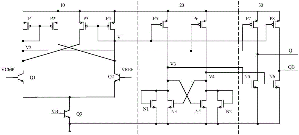
[0015] Please refer to figure 1 , 2 , in this embodiment, the voltage comparator 100 includes a first-stage amplifier circuit 10 with positive feedback, a second-stage latch circuit 20 and a three-stage Class A and B output circuit 30 .

[0016] The primary amplifier circuit 10 outputs a first voltage and a second voltage according to the input voltage at the input terminal. The primary amplifier circuit 10 includes two input terminals, one of which is used to input the first circuit to be compared VCMP, and the other input terminal is used to input the second circuit to be compared (ie, the reference voltage, VREF). The primary amplification circuit 10 amplifies the error signal between the first voltage to be compared VCMP and the referenc...


PUM


Abstract

The invention relates to a voltage comparator. The voltage comparator is provided with a positive-feedback first-stage amplification circuit, a second-stage latch circuit and a third-stage A and B type output circuit; the first-stage amplification circuit outputs first voltage and second voltage according to the input voltage of an input end; the input end of the second-stage latch circuit is connected with the output end of the first-stage amplification circuit, and the second-stage latch circuit outputs third voltage and fourth voltage according to the first voltage and the second voltage; and one part of the input ends of the third-stage A and B type output circuit are connected with the output end of the first-stage amplification circuit, and the other part of the input ends of the third-stage A and B type output circuit are connected with the input end of the second-stage latch circuit, and the third-stage A and B type output circuit generates corresponding digital logic signals according to the first voltage, the second voltage, the third voltage and the fourth voltage. The voltage comparator provided by the embodiments of the present invention has the advantage of low offset voltage, high gain, high speed and the like, and can satisfy a requirement for weak voltage signal recognition and will not generate signal distortion when converting voltage signals into digital logic signals.

Description

technical field [0001] Embodiments of the present invention relate to a comparison circuit, in particular to a voltage comparator. Background technique [0002] The IGBT driver chip is a signal transmission system composed of light-emitting diodes and photodiodes. Generally, the light-emitting diode and the receiving circuit of the integrated photodiode are packaged together. Since the optical signal received by the integrated photodiode is very weak, it is easy to generate signal distortion when converted into a digital logic signal. Contents of the invention [0003] The purpose of the embodiment of the present invention is to provide a voltage comparator, which has the characteristics of low offset voltage, high gain, high speed, etc., which can meet the weak voltage signal recognition ability, and will not convert the voltage signal into a digital logic signal. The generation number is distorted. [0004] In one aspect, the present invention provides a voltage compa...

Claims


Application Information

Patent Timeline
Patent Type & Authority Applications(China)
IPC IPC(8): H03K5/24
CPCH03K5/2445
Inventor 田欢
Owner 深圳市英特源电子有限公司
Learn More