
An anti-rolling device and its bogie

A bogie and anti-roll technology, which is applied in the direction of the device for lateral relative movement between the underframe and the bogie, can solve the adverse effects of the safety, reliability, and stability of the bogie, and cannot guarantee the torsion of the anti-roll device. Consistent rod height, high height of anti-rolling device from rail surface, etc., to achieve the effect of improving the stress state of torsion bar, compact structure, and improving the stress state of torsion bar

Active Publication Date: 2019-09-27
ZHUZHOU ELECTRIC LOCOMOTIVE CO LTD
View PDF5 Cites 0 Cited by
  • Summary
  • Abstract
  • Description
  • Claims
  • Application Information

AI Technical Summary

Problems solved by technology

[0004] 2. The height of the whole set of anti-rolling device from the rail surface is high. During assembly, the relative position of the torsion bar and the frame is not easy to adjust, and maintenance and inspection are inconvenient
Moreover, since the torsion arm and the torsion rod are connected by a shrink fit, and the lower end of the torsion arm and the tension and compression rod is fitted with a conical surface, there is a problem of difficulty in disassembly in both ways.
[0005] 3. The bogie frame and car body are welded parts, with long weld seams and large areas, which can easily lead to welding deformation, and interference between the anti-roll device and the frame or car body often occurs
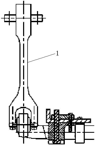
[0006] 4. If figure 1 As shown, the tension and compression bar 1 in the existing anti-roll device is an integral rod with a fixed length, which cannot be adjusted in height. The torsion bar produces additional torsional stress, which reduces the safety and reliability of the torsion bar structure
[0007] In summary, the anti-rolling device in the prior art has defects in reliability and stability, resulting in adverse effects on the safety, reliability and stability of the bogie after it is installed on the bogie

Method used


Image

  • An anti-rolling device and its bogie
  • An anti-rolling device and its bogie
  • An anti-rolling device and its bogie

Examples


Embodiment Construction

[0045] For the convenience of description, the description of the relative positional relationship of each component (such as: front, rear, etc.) is described according to the layout direction of the drawings in the specification, and does not limit the structure of this patent.

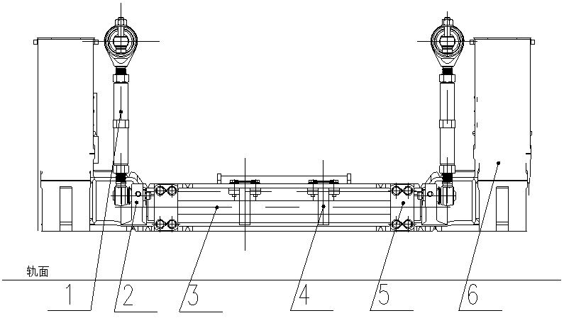
[0046] Such as Figure 2-6 As shown, an anti-rolling device includes a pair of tension and compression rods 1, a torsion arm 2 hinged to the lower end of each tension and compression rod 1, a torsion arm 2 arranged between the two torsion arms 2 and connected to the torsion arm 2. pole 3.

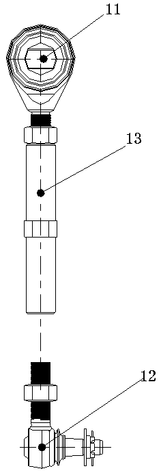
[0047] The tension and compression rod 1 is a telescopic tension and compression rod, and its structure includes an upper joint link 11 , a lower joint link 12 , and an intermediate link 13 connecting the upper joint link 11 and the lower joint link 12 .

[0048] The intermediate connecting rod 13 is threadedly connected with the upper joint connecting rod 11 and the lower joint connecting rod 12, and is fastened...


PUM


Abstract

The invention discloses a side rolling resistance device which comprises a pair of pull and press rods, torsional arms hinged to the lower ends of the pull and press rods, and a torsional rod which is arranged between the two torsional arms and is connected with the torsional arms, wherein the pull and press rods are telescopic pull and press rods. The invention further provides a steering frame. The pull and press rods are designed to be the telescopic form so that the perpendicular height can be convenient to adjust, and no extra torsional stress is generated so that the stress state of the torsional rod is improved, and the reliability of the side rolling resistance device is improved; furthermore, the side rolling resistance device is arranged on the inner side of a side beam of an architecture, so that the stress condition of the torsional rod is greatly improved; meanwhile, the side rolling resistance device further has the advantages of convenience for disassembling, no interference and the like.

Description

technical field [0001] The invention belongs to the technical field of rail transit vehicle equipment, and in particular relates to an anti-rolling device and a bogie thereof. Background technique [0002] In order to ensure the running stability and safety of the rail vehicle passing through the curve, the bogie is equipped with an anti-rolling device. The two tension and compression rods of the existing anti-rolling device are vertically arranged on both sides of the bogie frame, and the torsion rods are arranged above or below the crossbeam across the frame. The anti-rolling device of the prior art has the following defects: [0003] 1. Since the tension and compression rods are installed on the outside of the frame, the length of the torsion rod is longer and the rolling moment is larger. [0004] 2. The height of the whole set of anti-rolling device from the rail surface is high. During assembly, the relative position of the torsion bar and the frame is not easy to ad...

Claims


Application Information

Patent Timeline
Patent Type & Authority Patents(China)
IPC IPC(8): B61F5/24
Inventor 喻佳文晋军辉李茂春陶功安谢加辉
Owner ZHUZHOU ELECTRIC LOCOMOTIVE CO LTD
Learn More