
Internal combustion locomotive electric braking energy feedback converter and control method

An energy feedback, diesel locomotive technology, applied in electric braking systems, power management, current collectors, etc., can solve the problems of low power quality, braking energy consumption, occupying locomotive space, etc., to save equipment installation space, output High power quality and the effect of reuse

Active Publication Date: 2017-02-08
ZHUZHOU CSR TIMES ELECTRIC CO LTD
View PDF9 Cites 3 Cited by
  • Summary
  • Abstract
  • Description
  • Claims
  • Application Information

AI Technical Summary

Problems solved by technology

[0002] At present, the existing technology of diesel locomotives is: the diesel engine drives the auxiliary generator, and supplies power to the auxiliary system by controlling the excitation of the auxiliary generator; when braking with resistance, the braking energy is consumed through the braking resistor
The disadvantages of the above technologies are: a. The control is complicated and the power supply quality is not high; b. The space occupied by the locomotive affects the overall layout of the locomotive; c. The braking energy is all consumed in the braking resistor, which is not energy-saving and environmentally friendly.

Method used


Image

  • Internal combustion locomotive electric braking energy feedback converter and control method
  • Internal combustion locomotive electric braking energy feedback converter and control method
  • Internal combustion locomotive electric braking energy feedback converter and control method

Examples


Embodiment 1

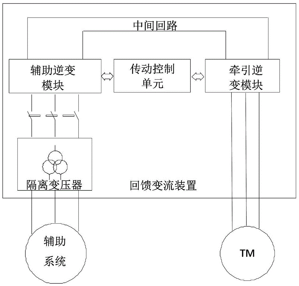
[0031] like figure 1 As shown, the diesel locomotive electric braking energy feedback converter device of this embodiment includes a traction inverter module, an auxiliary inverter module, an isolation transformer and a transmission control unit; the DC terminal of the traction inverter module communicates with the auxiliary inverter through an intermediate DC circuit. The DC terminal of the transformer module is connected; the AC terminal of the auxiliary inverter module is connected with the input side of the isolation transformer; the transmission control unit is connected with the traction inverter module and the auxiliary inverter module respectively.

[0032] In this embodiment, the transmission control unit includes a locomotive control parameter interface, a state parameter interface, and an electric energy state parameter interface. The locomotive control parameter interface is used to receive control parameters of the locomotive; The state parameter interface is used...

Embodiment 2

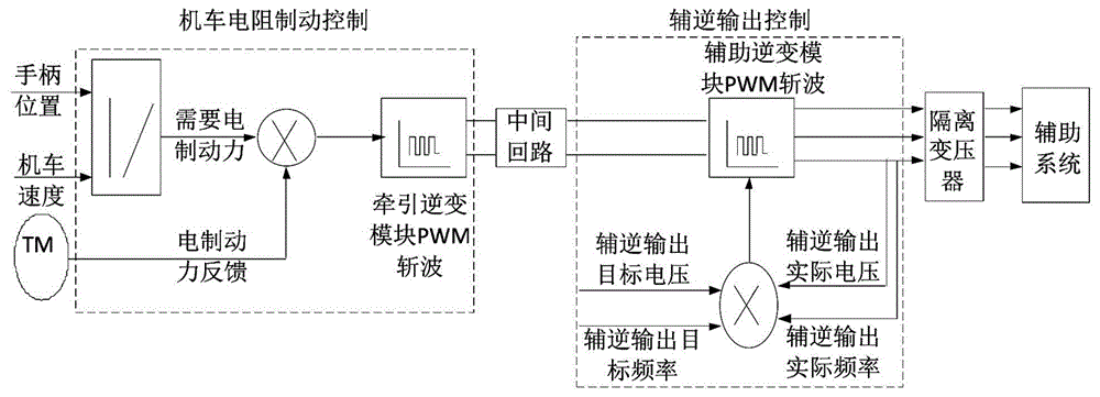
[0038]The electric braking energy feedback converter device of the diesel locomotive in this embodiment is the same as that in the first embodiment. The control method of the diesel locomotive electric braking energy feedback converter device of this embodiment is basically the same as that of Embodiment 1, the difference is that the specific steps of step S4 are: S4.2.1. Calculate the output target voltage of the auxiliary inverter module to determine the output target voltage of the auxiliary inverter module, and use the output target frequency of the isolation transformer as the output target frequency of the auxiliary inverter module; S4.2.2. The transmission control unit obtains the output actual voltage of the auxiliary inverter module and the actual output frequency of the auxiliary inverter module; S4.2.3. The transmission control unit uses the output actual voltage of the auxiliary inverter module and the output target frequency of the auxiliary inverter module accordi...


PUM


Abstract

The invention discloses an internal combustion locomotive electric braking energy feedback converter which comprises a traction inversion module, an auxiliary inversion module, an isolation transformer and a transmission control unit, wherein the direct current end of the traction inversion module is connected with the direct current end of the auxiliary inversion module through an intermediate direct current circuit; the alternating current end of the auxiliary inversion module is connected with the input side of the isolation transformer; and the transmission control unit is respectively connected with the traction inversion module and the auxiliary inversion module. The internal combustion locomotive electric braking energy feedback converter does not need an auxiliary power generator or an auxiliary motor excitation control system, is used for supplying power to an auxiliary system by utilizing locomotive braking energy feedback, has the advantages of locomotive space saving, energy conservation, environmental friendliness and accurate control, and can be used for supplying high-quality electric energy to the auxiliary system.

Description

technical field [0001] The invention relates to the field of braking energy feedback of internal combustion locomotives, in particular to an electric braking energy feedback conversion device and control method for internal combustion locomotives. Background technique [0002] At present, the existing technology for diesel locomotives is: the diesel engine drives the auxiliary generator, and supplies power to the auxiliary system by controlling the excitation of the auxiliary generator; when braking with resistance, the braking energy is consumed through the braking resistor. The disadvantages of the above technologies are: a. The control is complicated and the power supply quality is not high; b. The space occupied by the locomotive affects the overall layout of the locomotive; c. The braking energy is all consumed in the braking resistor, which is not energy-saving and environmentally friendly. Contents of the invention [0003] The technical problem to be solved by the ...

Claims


Application Information

Patent Timeline
Patent Type & Authority Applications(China)
IPC IPC(8): B60L7/10B60L1/00
CPCB60L1/00B60L7/10Y02T10/72
Inventor 李小文何良
Owner ZHUZHOU CSR TIMES ELECTRIC CO LTD
Learn More