
A stamping die pulling device

A stamping die and material hole technology, which is applied in the field of stamping die pulling device, can solve the problems of poor operation stability, high production cost, and easy bending, etc., and achieve the effects of stable operation, simple structure, and improved stamping efficiency

Active Publication Date: 2018-09-07
今朝联合有限公司
View PDF7 Cites 0 Cited by
  • Summary
  • Abstract
  • Description
  • Claims
  • Application Information

AI Technical Summary

Problems solved by technology

[0004] The purpose of the present invention is to overcome the deficiencies of the prior art, to overcome the original push-type feeding method in the stamping process, which makes the thinner stamping material easy to bend, and the existing pulling device has a complex structure, high manufacturing cost, and stable operation To solve the problem of poor performance, provide a stamping die pulling device

Method used


Image

  • A stamping die pulling device
  • A stamping die pulling device
  • A stamping die pulling device

Examples


Embodiment

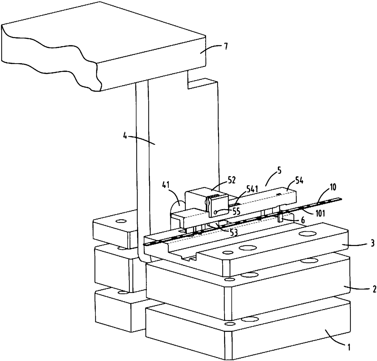
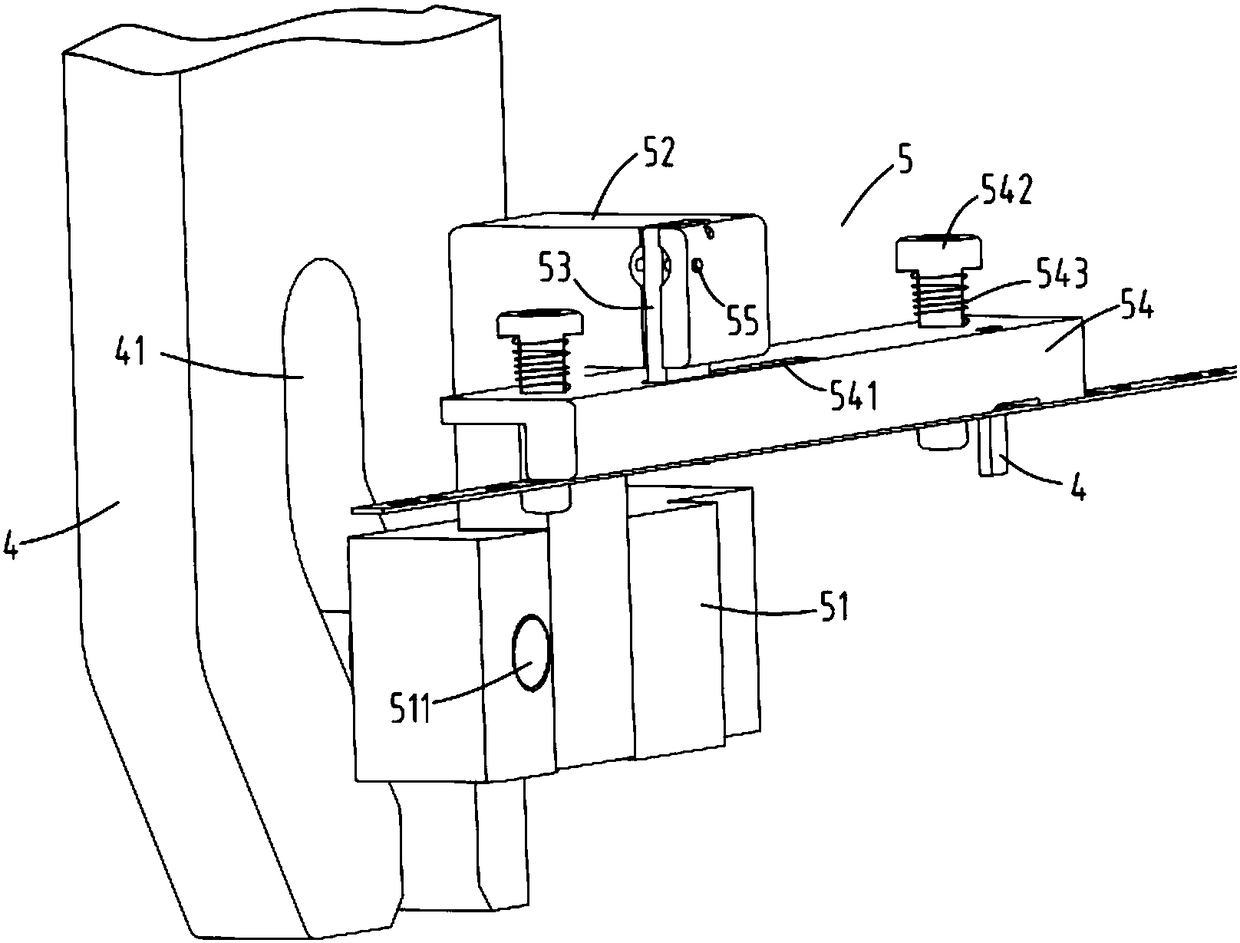
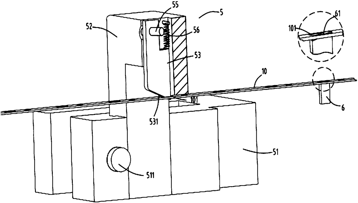
[0024] figure 1 A schematic diagram of the drawing device for the stamping die, figure 2 It is a schematic diagram of the transmission block and the hooking part, image 3 It is a schematic diagram of the inside of the hooking part, Figure 4 It is a schematic diagram of the base, guide seat and mounting seat. Such as figure 1 , figure 2 , image 3 and Figure 4 As shown, what is provided in this embodiment is a stamping die pulling device, including a base 1, a guide seat 2, a mounting seat 3, a transmission block 4, and a hooking part 5; the guide seat 2 is arranged on the base 1; The mounting seat 3 is arranged on the guide seat 2; the hooking part 5 is arranged on the mounting seat 3; Slide up and down with the mounting base 3; when the transmission block 4 moves up and down, the curved waist hole 41 arranged at the lower end of the transmission block 4 drives the material hook part 5 to move back and forth to pull the material block 10; the material hook part 5 i...


PUM


Abstract

The invention relates to a stamping die material pulling device. The stamping die material pulling device comprises a base, a guide seat, an installation seat, a transmission block and a material hooking part, wherein the guide seat is arranged on the base; the installation seat is arranged on the guide seat; the material hooking part is arranged on the installation seat; the transmission block longitudinally penetrates through the base, the guide seat and the installation seat and slides vertically relative to the base, the guide seat and the installation seat; and when the transmission block moves vertically, a curved type kidney-shaped hole in the lower end of the transmission block is used for driving the material hooking part to move forwards and backwards to pull a material block. The problems that in the stamping process, through an original pushing type material feeding method, a relatively thin stamping material is prone to bending, and an existing material pulling device is complex in structure, high in manufacturing cost and poor in operation stability are solved.

Description

technical field [0001] The invention relates to the technical field of stamping equipment, in particular to a material pulling device for a stamping die. Background technique [0002] In the existing process, stamping dies are usually used to stamp and form metal strips to make small hardware parts. Usually, the speed of the punch’s up and down movement is relatively high, and the stamping strip needs to be able to realize automatic high-speed feeding in order to ensure the accuracy of the stamping material. The corresponding shape is continuously punched out on the belt at high speed. Most of the feeding methods in the prior art belong to the push type. For the thinner thickness of the stamping material belt, because the belt itself is prone to bending, it is easy to form an arch in front of the stamping die. The shape affects the feeding. [0003] A Chinese patent with the authorized publication number CN201848487U discloses a stamping and pulling machine. By setting the ...

Claims


Application Information

Patent Timeline
Patent Type & Authority Patents(China)
IPC IPC(8): B21D43/02B21D37/10
CPCB21D37/10B21D43/02
Inventor 厉海飞
Owner 今朝联合有限公司
Learn More