Rotary flume test device for making small debris flow

A technology for rotating a water tank and a test device, which is applied to teaching models, educational appliances, instruments, etc., can solve the problems of small shooting angle, cumbersome structure, troublesome device production, etc., and achieves the effect of large shooting angle, high test accuracy and simple structure.

Pending Publication Date: 2017-02-01
SHANGHAI JIAO TONG UNIV
View PDF9 Cites 6 Cited by
  • Summary
  • Abstract
  • Description
  • Claims
  • Application Information

AI Technical Summary

Problems solved by technology

[0008] The technical problem to be solved in the present invention is: in the existing rotating water tank experimental device for making debris flow, in order to solve the problem of debris flow sticking to the bottom of the tank, a slide plate must be installed, resulting in simulation distortion; the shooting angle range of the camera is only the arc surface of the bottom of the tank One section, the shooting angle is small, and the thickness of the debris flow cannot be obtained by taking images; the diameter and volume of the rotating water tank are large, the structure is heavy, and due to the limitations of the structure of the skateboard, frame, camera, etc., the size is difficult to reduce, resulting in troublesome production of the device and cost Higher, the experimental accuracy is also difficult to improve

Method used


Image

  • Rotary flume test device for making small debris flow
  • Rotary flume test device for making small debris flow
  • Rotary flume test device for making small debris flow

Examples


Embodiment Construction

[0029] The present invention will be further described below in conjunction with the accompanying drawings and specific implementation.

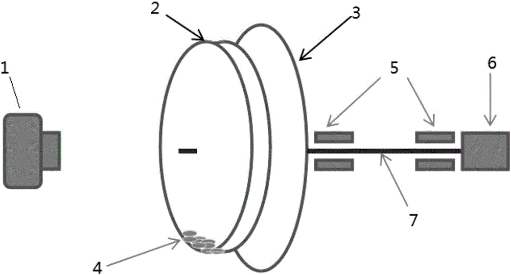
[0030] see image 3 , a rotating water tank test device for making small-scale debris flow, including a rotating water tank 2 made of smooth and transparent material. Structure: An opaque background disk 3 is fixedly arranged behind the rotating water tank 2, and one end of the transmission shaft 7 of the background disk passes through the background disk 3 and is fixedly connected with the axis of the rotating water tank 2, and the other end is connected with the rotating power device 6 A camera 1 is fixedly installed in front of the rotating water tank 2 ;

[0031] see image 3 , There is a smooth arc transition between the bottom surface and the side surface of the rotating water tank 2 .

[0032] see image 3 , the camera 1 is arranged coaxially with the rotating water tank 2, and takes a global picture of the entire front of the rot...


PUM


Abstract

The invention relates to a rotary flume test device for making a small debris flow. The test device comprises a rotary flume which is made from a smooth and transparent material, wherein the rotary flume is represented as a sealed cylindrical structure and the rotary flume is of an integrated structure which is formed by splicing a pair of cylinder bodies which are opened in a unidirectional mode; a non-transparent background disc is fixedly arranged at the back of the rotary flume; as for the background disc, one end of a transmission shaft runs through the background disc and is fixedly connected to the axis of the rotary flume and the other end is connected to a rotary power device; and a camera is fixedly arranged at the front side of the rotary flume. The rotary flume test device provided by the invention is small in overall dimensions; the flume is completely made from organic glass, so that the made debris flow is free from a phenomenon of bottom bonding; the rotary flume test device is simple in structure, convenient for making the debris flow and relatively low in cost; the rotary flume is represented as the integrated structure which is made from the transparent and smooth material, and the made debris flow, which is free from the phenomenon of bottom bonding, is closer to a field debris flow; and the camera, which can conduct overall shooting from the front side, has a large shooting viewing angle, and the thickness of the debris flow can be obtained by shooting a head.

Description

technical field [0001] The invention relates to a small-scale mud-rock flow rotating water tank experimental device for observing the movement of mud-rock flow, and belongs to the technical field of test devices for making mud-rock flow. Background technique [0002] There are two methods for making debris flow in the prior art laboratory, one of which is a common water tank test, and the other is a rotating water tank test. [0003] The disadvantage of the common tank test is that the tank test produces debris flow ( figure 1 ), but tanθ cannot be equal to the resistance gradient J of all solid particles, and the flow may have problems such as solid-liquid phase separation, so even if the overall average flow velocity v can remain unchanged, the solid There may also be a large relative movement between the two liquid phases along the process, resulting in changes in resistance, impact force, and shear force at the bottom of the tank along the process, which brings difficul...

Claims


Application Information

Patent Timeline
Patent Type & Authority Applications(China)
IPC IPC(8): G09B25/00
CPCG09B25/00
Inventor 邓检良
Owner SHANGHAI JIAO TONG UNIV
Why Eureka
Try Eureka