Method and system for counting banknotes in banknote-conveying process
A counting method and banknote technology, applied in the complete banking system, complete banking system, handling coins or valuable banknotes, etc., can solve problems such as banknote reporting errors, inaccurate counting, sensor counting interference, etc., and achieve counting results The effect of correctness, reducing the reporting of wrong information such as banknote jams, and reducing the downtime rate
- Summary
- Abstract
- Description
- Claims
- Application Information
AI Technical Summary
Problems solved by technology
Method used
Image
Examples
Embodiment 1
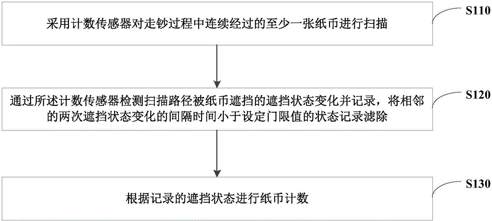
[0025] figure 1 It is a flow chart of a banknote counting method in the process of banknote transfer provided by Embodiment 1 of the present invention. This embodiment is applicable to the situation where each module in the automatic deposit and withdrawal machine counts banknotes. The banknote counting system in the process can be implemented by means of software and / or hardware, and is generally integrated in the cash machine. The method specifically includes:
[0026] S110, using a counting sensor to scan at least one banknote that passes continuously during the banknote feeding process.
[0027] Specifically, the counting sensor may be a counting sensor at any location such as the customer receiving section, the temporary storage section, or inside the cash box.
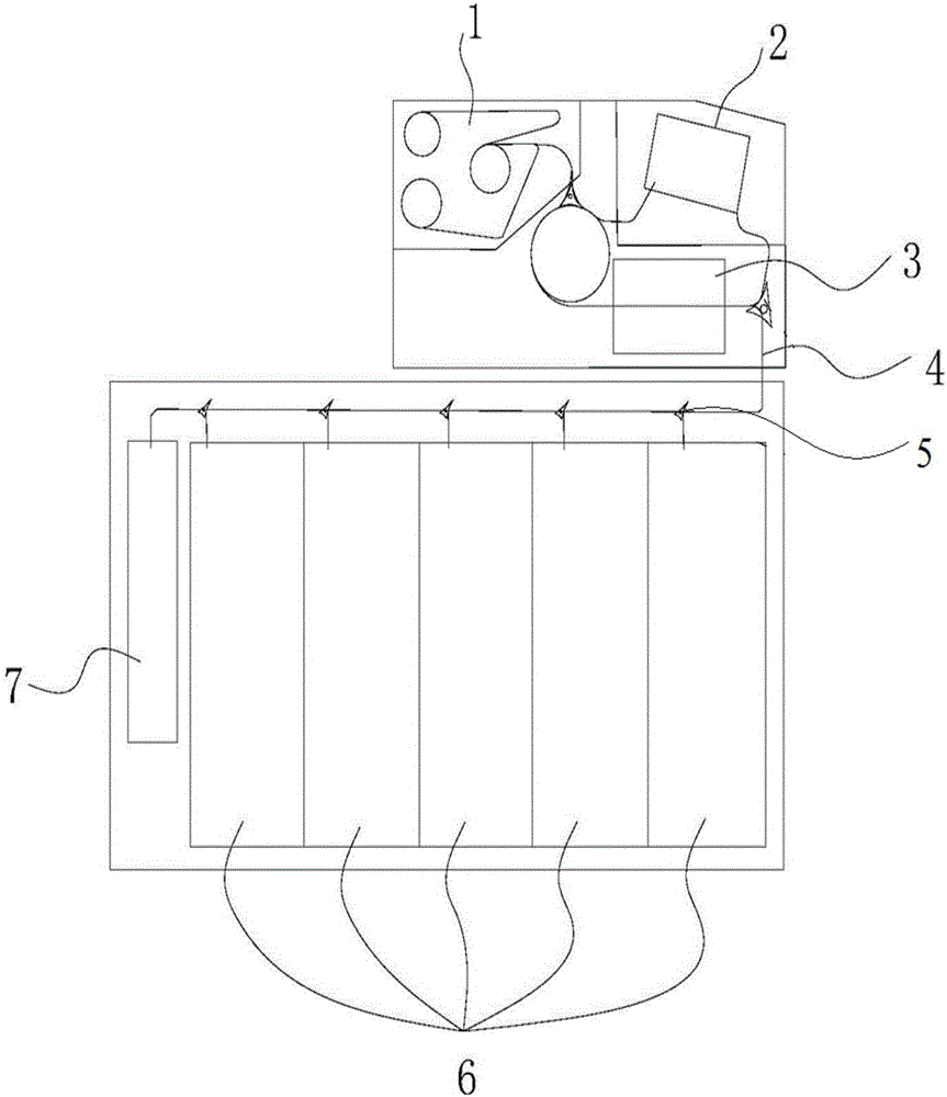
[0028] specific, figure 2 It is a schematic diagram of the banknote-moving process provided in Embodiment 1 of the present invention. The example of the banknote-moving process of some banknotes is as follow...
Embodiment 2
[0036] Figure 5 It is a flow chart of a banknote counting method in the process of banknote transfer provided in Embodiment 2 of the present invention. On the basis of the previous embodiment, this embodiment differs from the preceding embodiment in that the counting method will The sensor detects and records the change of the blocking state that the scanning path is blocked by banknotes, and filters out the state records where the interval between two adjacent blocking state changes is less than the set threshold value, and further refines it into specific implementation steps. Combine below Figure 5 A banknote counting method in the process of banknote removal provided by Embodiment 2 of the present invention is described, including the following steps:
[0037] S510, using a counting sensor to scan at least one banknote that passes continuously during the banknote feeding process.
[0038] S520. Detect and record the blocking state of the banknote.
[0039] S530. Deter...
Embodiment 3
[0057] Figure 6 It is a schematic diagram of a banknote counting system in the process of banknote transfer. Specifically, the system includes:
[0058] The banknote scanning module 610 uses a counting sensor to scan at least one banknote that passes continuously during the banknote removal process;
[0059] The blocking state recording module 620 is used to detect and record the blocking state change that the scanning path is blocked by banknotes through the counting sensor, and filter out the state records that the interval between two adjacent blocking state changes is less than the set threshold value;
[0060] The banknote counting module 630 is used for counting banknotes according to the recorded blocking state.
[0061] Further specifically, the occlusion state recording module is specifically used to execute:
[0062] Step A: Use the counting sensor to detect whether the state of the scan path has a change in occlusion. If the state change is detected as occlusion...
PUM
 Abstract
Description
Claims
Application Information
 - R&D
- Intellectual Property
- Life Sciences
- Materials
- Tech Scout
- Unparalleled Data Quality
- Higher Quality Content
- 60% Fewer Hallucinations
Browse by: Latest US Patents, China's latest patents, Technical Efficacy Thesaurus, Application Domain, Technology Topic, Popular Technical Reports.
© 2025 PatSnap. All rights reserved.Legal|Privacy policy|Modern Slavery Act Transparency Statement|Sitemap|About US| Contact US: help@patsnap.com


