Heat pipe type vacuum dryer

A vacuum dryer and heat pipe technology, applied in non-progressive dryers, dryers, drying chambers/containers, etc., can solve the problems of uneven drying of wet materials, affecting the drying quality of materials, etc., and achieve optimal drying effect. , The effect of shortening the drying time and increasing the total amount of heat energy transmission

Inactive Publication Date: 2017-02-01
张国利
View PDF0 Cites 4 Cited by
  • Summary
  • Abstract
  • Description
  • Claims
  • Application Information

AI Technical Summary

Problems solved by technology

Wet materials often form agglomerates in a vacuum state, resulting in uneven drying of wet materials and affecting the drying quality of materials

Method used


Image

  • Heat pipe type vacuum dryer
  • Heat pipe type vacuum dryer
  • Heat pipe type vacuum dryer

Examples


Embodiment

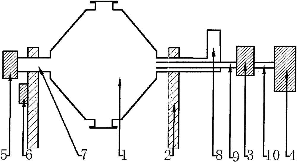
[0021] Such as figure 1 A heat pipe type vacuum dryer shown is composed of a heat pipe type drying chamber (1), a support (2), a condenser (3), a vacuum pump (4), a heating device (5), a driving device (6), an air duct ( 10) Composition.

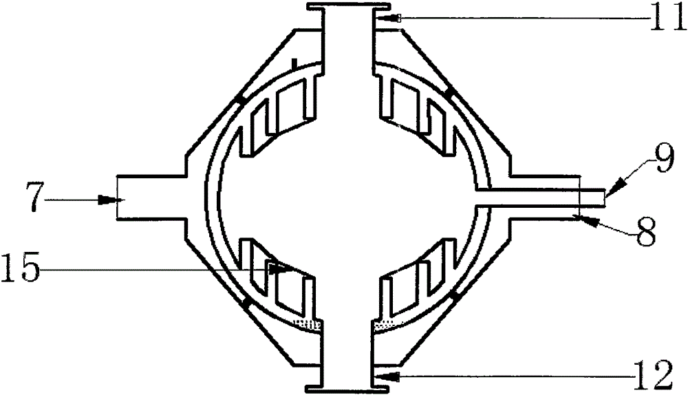
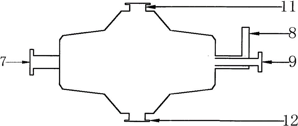
[0022] The appearance shape of the heat pipe type drying chamber (1) is biconical or cylindrical.

[0023] The thermal energy inlet (7) and thermal energy outlet (8) at both ends of the heat pipe type drying chamber (1) are installed on the support (2).

[0024] The driving device (6) is installed on the bracket (2), and the driving device (6) is used to drive the heat pipe type drying chamber (1) to rotate.

[0025] The thermal energy inlet (7) of the heat pipe type drying warehouse (1) is connected to the heating device (5) through the air duct (10); the heat energy outlet (8) of the heat pipe type drying warehouse (1) is connected through the air duct (10) to the heating unit (5).

[0026] The heating device (5) is a boiler.

[0027]...


PUM


Abstract

The invention discloses a heat pipe type vacuum dryer composed of a heat pipe type drying bin, a support, a condenser, a vacuum pump, a heating device, a driving device and a gas guiding pipe. The two ends of the heat pipe type drying bin are installed on the support, and according to the appearance shape, the heat pipe type drying bin is in the shape of double cones, a sphere or a cylinder. A heat energy inlet and a heat energy outlet of the heat pipe type drying bin are connected to the heating device through the gas guiding pipe. A gas exhausting port of the heat pipe type drying bin is connected to the condenser and the vacuum pump through the gas guiding pipe, and the atmospheric pressure in the heat pipe type drying bin reaches the vacuum degree of -0.094 Mpa to -0.098 Mpa. According to the heat pipe type vacuum dryer, the inner wall single layer plane cooling of the drying bin is changed into the inner wall stereoscopic cooling of the drying bin, the cooling area is increased by 5-30 times, the heat guiding and dissipating speed is increased, the drying time is shortened, continuous stirring and crushing can be achieved, the drying efficiency is improved, and the drying effect is optimized; and the effects of using waste heat, saving energy and reducing emission are achieved.

Description

technical field [0001] The invention relates to a vacuum dryer for drying materials, in particular to a heat pipe vacuum dryer. Background technique [0002] Most of the vacuum drying devices and double-cone vacuum dryers on the market now use the single-layer plane of the inner wall of the outer interlayer for heat dissipation and heating. The heat dissipation area is small, the contacting surface of the material is smaller, and the efficiency of heat energy use is low. The wet material is in a vacuum state, and the air pressure drops so that the water (solvent) on the surface of the material can evaporate quickly, and it will be discharged and recovered by the vacuum unit in time, so as to achieve the purpose of drying. Wet materials often form agglomerates under vacuum, which causes uneven drying of wet materials and affects the drying quality of materials. Contents of the invention [0003] The problem to be solved by the present invention is to overcome the deficienc...

Claims


Application Information

Patent Timeline
Patent Type & Authority Applications(China)
IPC IPC(8): F26B11/06F26B23/10F26B25/16
CPCY02P70/10
Inventor 张国利
Owner 张国利
Why Eureka
Try Eureka