
Chemical raw material drying device with spiral discharge device

A technology for chemical raw materials and screw discharge, which is used in dryers for static materials, dry solid materials, and dry goods processing. Reasonable design and simple structure

Active Publication Date: 2017-02-01
JIANSU JINSHAN BEER RAW MATERIAL CO LTD
View PDF9 Cites 10 Cited by
  • Summary
  • Abstract
  • Description
  • Claims
  • Application Information

AI Technical Summary

Problems solved by technology

[0002] At present, with the development of science and technology, the fields of industry and coal mining are also developing rapidly. In industrial processing and production, it is often necessary to dry some materials to prevent the moisture contained in the materials from affecting the later processing. It is often necessary to add some chemical raw materials to some chemical raw materials so that the chemical raw materials can be fully mixed with other raw materials. However, due to the unreasonable structural design of the existing material drying device, the material cannot be fully dried during the drying process. The surface of the dried material still contains moisture, and the drying efficiency is poor, the work efficiency is low, and it is difficult to remove the chemical raw material during discharge, which greatly reduces the utilization rate of the chemical raw material

Method used


Image

  • Chemical raw material drying device with spiral discharge device
  • Chemical raw material drying device with spiral discharge device
  • Chemical raw material drying device with spiral discharge device

Examples


Embodiment Construction

[0015] The technical solution of this patent will be further described in detail below in conjunction with specific embodiments.

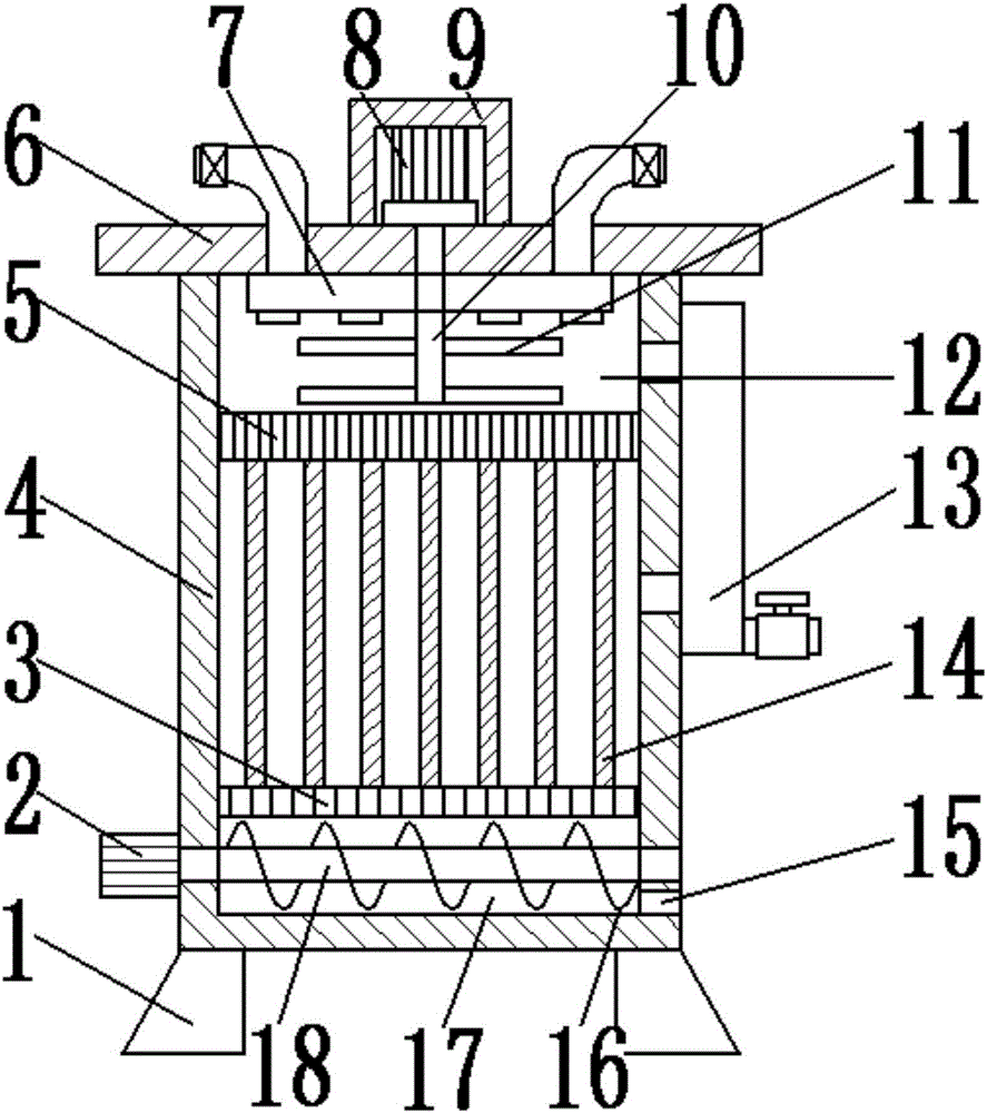
[0016] see Figure 1-3 , a chemical raw material drying device with a screw discharge device, comprising a base 1; the top of the base 1 is provided with a discharge bin 17, which is convenient for staff to install the device and can ensure the stability of the device; The inside of the discharge bin 17 is provided with a stirring shaft 18 and a stirring paddle 16, the right side of the discharge bin 17 is provided with a discharge port 15, and the top of the discharge bin 17 is provided with a heating filter plate 3 for drying Afterwards, the chemical materials are discharged; the stirring shaft 18 is arranged on the center line of the discharge bin 17, and the left end runs through the inner wall on the left side of the discharge bin 17, and is connected with the discharge motor 2; the discharge motor 2 is arranged on the discharge On the left o...


PUM


Abstract

The invention discloses a chemical raw material drying device with a spiral discharge device. The chemical raw material drying device comprises a base; a discharge bin is arranged on the top of the base; a heating filter plate is arranged on the top of the discharge bin; a drying box is arranged on the top of the heating filter plate; a drying plate is arranged inside the drying box; the bottom of the drying plate is connected with the heating filter plate; the top end of the drying plate is connected with a flow-splitting plate; the flow-splitting plate is arranged on the top of the drying box; a charge bin is arranged on the top of the flow-splitting plate; and a crushing shaft, crushing blades and a charge device are arranged inside the charge bin. The chemical raw material drying device disclosed by the invention is simple in structure, is reasonable in design and is convenient to use; the flow-splitting plate is arranged, so that chemical raw materials can be uniformly discharged and are not input to be clustered, and therefore, the drying device can be used for drying more conveniently; a gas exhaust device is arranged, so that water vapor generated in a drying process can be exhausted; and a drying plate and a drying box can be arranged for drying materials, so that the materials are dried completely.

Description

technical field [0001] The invention relates to chemical drying equipment, in particular to a chemical raw material drying device with a screw discharge device. Background technique [0002] At present, with the development of science and technology, the fields of industry and coal mining are also developing rapidly. In industrial processing and production, it is often necessary to dry some materials to prevent the moisture contained in the materials from affecting the later processing. It is often necessary to add some chemical raw materials to some chemical raw materials so that the chemical raw materials can be fully mixed with other raw materials. However, due to the unreasonable structural design of the existing material drying device, the material cannot be fully dried during the drying process. The surface of the dried material still contains moisture, and the drying efficiency is poor, the work efficiency is low, and it is difficult to remove the chemical raw materia...

Claims


Application Information

Patent Timeline
Patent Type & Authority Applications(China)
IPC IPC(8): F26B9/06F26B25/00F26B25/04
CPCF26B9/06F26B25/001F26B25/04
Inventor 不公告发明人
Owner JIANSU JINSHAN BEER RAW MATERIAL CO LTD
Learn More