Connecting structure of main shaft and rotor and integrated rolling rotor compressor

A technology of connecting structure and rolling rotor, applied in the field of compressors, can solve the problem that the crankshaft and the rotor cannot be fastened.

Inactive Publication Date: 2017-02-01
ZHUHAI GREE REFRIGERATION TECH CENT OF ENERGY SAVING & ENVIRONMENTAL PROTECTION
View PDF8 Cites 0 Cited by
  • Summary
  • Abstract
  • Description
  • Claims
  • Application Information

AI Technical Summary

Problems solved by technology

[0005] The technical problem to be solved by the present invention lies in the fact that the assembly structure of the crankshaft and the rotor in the prior art cannot be fastened in the axial direction, so a kind of assembly structure of the main shaft and the rotor that can be fastened and assembled in the circumferential direction and the axial direction is proposed. connection structure

Method used


Image

  • Connecting structure of main shaft and rotor and integrated rolling rotor compressor
  • Connecting structure of main shaft and rotor and integrated rolling rotor compressor
  • Connecting structure of main shaft and rotor and integrated rolling rotor compressor

Examples


Embodiment 1

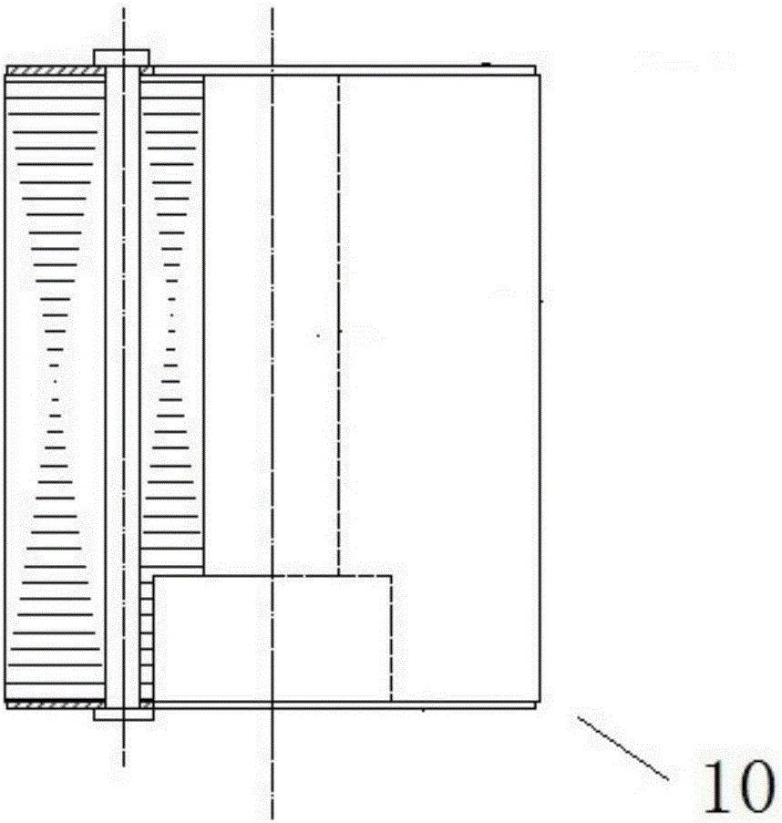
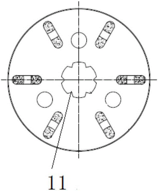
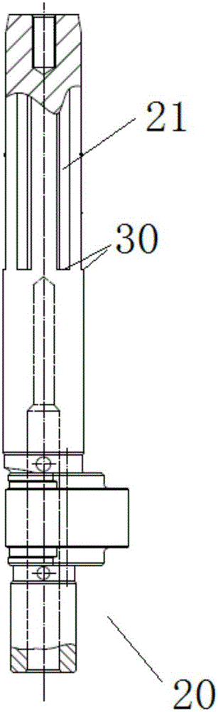
[0038] This embodiment provides a connection structure between the main shaft and the rotor of an integrated rolling rotor compressor, such as Figure 6 As shown, it includes: a rotor 10 and a main shaft 20, the circumferential wall of the main shaft 20 is provided with a circumferential fixing part that cooperates with the concave and convex inner wall of the rotor 10; the end surface of the main shaft 20 is provided with a 10 axial fixing members. The circumferential fixing part and the axial fixing member make the main shaft 20 and the rotor 10 fastened not only in the circumferential direction, but also in the axial direction, so as to prevent the rotor 10 and the main shaft 20 from being damaged during the rotation of the main shaft 20 and the rotor 10. Relative movement along the axial direction separates from each other.

[0039] Axial fixing components include: such as Figure 6 As shown in , the baffle 40 for restricting the axial movement of the rotor 10 relative t...

Embodiment 2

[0048] The connection structure between the main shaft and the rotor of an integrated rolling rotor compressor provided in this embodiment includes: a rotor 10 and a main shaft 20, the circumferential wall of the main shaft 20 is axially extended and formed with convex teeth, and the inner circular wall of the rotor 10 Grooves are formed on the top to cooperate with the convex teeth, and the cooperation between the convex teeth and the grooves realizes the fastening and linkage setting of the main shaft 20 and the rotor 10 in the circumferential direction, so that when the rotor 10 rotates, the main shaft 20 can be driven to be linked to realize The linkage between the motor output shaft and the compressor crankshaft. An axial fixing member for axially fixing the rotor 10 is arranged on the end surface of the main shaft 20 . Therefore, the main shaft 20 and the rotor 10 are fastened not only in the circumferential direction, but also in the axial direction, so as to prevent th...

Embodiment 3

[0051] An integrated rolling rotor compressor provided in this embodiment includes a motor part and a compressor part, and the two parts are connected together through a main shaft 20 that is used as both the output shaft of the motor and the crankshaft of the compressor, such as Figure 6 As shown, the connection structure between the main shaft 20 and the rotor 10 is the connection structure described in the above-mentioned embodiment 1 or embodiment 2, so it has all the advantages of the above-mentioned embodiment 1 or embodiment 2.


PUM


Abstract

The invention discloses a connecting structure of a main shaft and a rotor and an integrated rolling rotor compressor and belongs to the technical field of compressors. The connecting structure of a main shaft and a rotor comprises the rotor and the main shaft; a circumferential fixing part in concave-convex match with the inner circle wall of the rotor is arranged on the circumferential wall of the main shaft; and an axial fixing component for fixing the rotor in the axial direction is arranged on the end face of the main shaft, so that the main shaft and the rotor are fastened both in the circumferential direction and the axial direction to prevent mutual separation due to relative movement of the rotor and the main shaft in the axial direction during the rotating process of the main shaft and the rotor.

Description

technical field [0001] The invention relates to a connection structure between a main shaft and a rotor, and a compressor using the connection method between the main shaft and the rotor, belonging to the technical field of compressors. Background technique [0002] The compressor is a mechanical device that raises low-pressure gas to high-pressure gas driven by the power unit. The integrated rolling rotor compressor includes a motor part and a compressor part. The two parts are used as both the output shaft of the motor and the compressor The main shafts of the machine crankshaft are connected together. Its rotor cooperates with the main shaft to transmit mechanical energy. Existing compressor rotors and main shafts are fixed by interference fit. During the production process, the rotor needs to be heated for thermal sleeve and then cooled, so that the rotor and main shaft can achieve interference fit. However, due to the need to heat the rotor, heating equipment and cool...

Claims


Application Information

Patent Timeline
IPC IPC(8): F04C29/00
CPCF04C29/0078
Inventor 樊峰刚韩鑫彭慧明曹彭杰金冀龙白璐琛赵旭敏
Owner ZHUHAI GREE REFRIGERATION TECH CENT OF ENERGY SAVING & ENVIRONMENTAL PROTECTION
Why Eureka
Try Eureka