
Distributed unmanned aerial vehicle charging machine hangar

A kind of unmanned aerial vehicle and distributed technology, applied in the direction of current collectors, electric vehicles, electrical components, etc., can solve the problems of energy bottleneck, short flight distance, short flight time, etc. effect of ability

Pending Publication Date: 2017-02-01
上海含骏自动化设备有限公司
View PDF1 Cites 20 Cited by
  • Summary
  • Abstract
  • Description
  • Claims
  • Application Information

AI Technical Summary

Problems solved by technology

However, the current bottlenecks of multi-rotor UAVs are short flight time (within 30 minutes) and short flight distance (within 2km), which often causes people to run randomly and constantly replace batteries, etc.
UAVs have achieved a certain degree of human capital reduction, but due to energy bottlenecks, it is impossible to truly achieve unmanned mission execution
[0003] For example, the patent document (CN 205178593U) proposes a platform idea for using solar energy to charge UAVs, but the concept of UAV usage scenarios is insufficient, and it only meets the requirements of charging without considering the protection of UAVs in unmanned states. , communication, practical value is not high

Method used


Image

  • Distributed unmanned aerial vehicle charging machine hangar
  • Distributed unmanned aerial vehicle charging machine hangar
  • Distributed unmanned aerial vehicle charging machine hangar

Examples


Embodiment Construction

[0030] In order to make the object, technical solution and advantages of the present invention clearer, the present invention will be further described in detail below with reference to the accompanying drawings as an example. It should be understood that the specific implementation methods described here are only used to explain the present invention, not to limit the present invention.

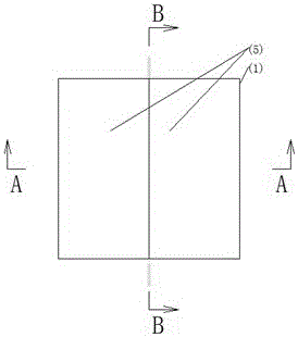
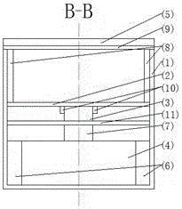
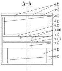
[0031] The UAV charging hangar includes hangar protection box (1), apron (2), wireless charging module (3), single-chip microcomputer (4), solar panel with sliding cover (5), battery pack (6) , GPS / Beidou positioning communication module (7).

[0032] The single-chip microcomputer (4), the solar battery panel (5) and the battery pack (6) form a primary charging system, and the solar battery panel (5) is used to store solar energy in the battery. The wireless charging module (3) and the storage battery pack (6) form a secondary charging system, which charges the electric energy of the storag...


PUM


Abstract

The invention discloses a distributed unmanned aerial vehicle charging machine hangar which comprises a machine hangar protection box body, a parking apron, a wireless charging module, a single chip microcomputer, a solar cell panel with a slidable cover, a storage battery pack and a GPS / Beidou positioning communication module, wherein the single chip microcomputer, the solar cell panel and the storage battery pack form a primary charging system, solar energy is stored in storage batteries by utilizing the solar cell panel, the wireless charging module and the storage battery pack form a secondary charging system, electric energy of the storage battery pack is charged to an unmanned aerial vehicle in an electricity shortage state, the single chip microcomputer controls the state of the slidable cover of the solar cell panel and closes the solar cell panel to protect the unmanned aerial vehicle or opens the solar cell panel for berthing or taking off of the unmanned aerial vehicle. Therefore, the hangar has the functions of berthing, protection, charging, positioning communication and the like of the unmanned aerial vehicle. Due to the fact that the solar cell panel is arranged, the hangar can be arranged in a field in a distributed mode and can accommodate several unmanned aerial vehicles. The distributed unmanned aerial vehicle charging machine hangar has the advantages of being free of maintenance, long in service, usable in an offline mode and the like.

Description

technical field [0001] The invention relates to the technical field of multi-rotor drones, in particular to a charging hangar for drones. Background technique [0002] Multi-rotor UAV is a kind of UAV with hover function, which has developed rapidly in recent years. There are more and more applications in aerial photography, maintenance inspection, plant protection, short-term monitoring and other fields. Especially for large-area unattended and extremely harsh environments (such as reservoirs and power stations), it replaces manual on-duty and observation, which greatly reduces the risk and cost of work while increasing work efficiency. It is a very potential application. . However, the current bottleneck of multi-rotor drones is short flight time (within 30 minutes) and short flight distance (within 2km), which often causes people to run randomly and constantly replace batteries. UAVs have achieved a certain degree of human capital reduction, but due to energy bottlenec...

Claims


Application Information

Patent Timeline
IPC IPC(8): E04H6/44H02J7/35H02J50/12
CPCH02J7/025H02J7/35E04H6/44
Inventor 任连萌戴维
Owner 上海含骏自动化设备有限公司
Learn More