


Quick Research
Generate reliable direction feasibility study reports for your R&D in just a few steps.

Technical Q&A
Discover and master advanced knowledge NOW. Basics, ideas, possibilities, all at once.

Find Solutions
As an expert in R&D theories, this can generate solutions to your technical problems instantly.

Evaluate Feasibility
Analyze your overall solution with one click, know your potential R&D risks in advance.

Monitor Landscape
Get weekly tech updates, stay abreast of the latest tech innovations and key insights.
Pulling force measuring device
A strength and strut technology, applied in the field of mobile phone touch display, can solve the problems of high equipment cost and long equipment layout, and achieve the effect of reducing production cost, saving test time and saving space
- Summary
- Abstract
- Description
- Claims
- Application Information
AI Technical Summary
Problems solved by technology
Method used
Image


Examples
specific Embodiment approach 1
[0031] In this embodiment figure 1 It shows the working state diagram of testing the adhesion between the FPC and the cell by the existing tension equipment, in which the test end of the existing tension equipment is attached to the FPC5. figure 2 It shows the working state diagram of testing the adhesion between TP and LCM by the existing tension equipment, in the figure, the test end of the existing tension equipment is closely attached to the junction between TP7 and LCM8.
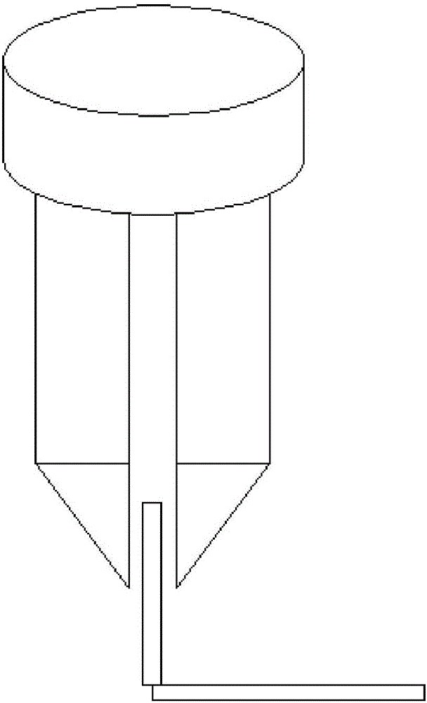
[0032] This embodiment comprises a connecting block 1, an L-shaped block 2, a rod-shaped fastener 3 and two movable struts 4, and two movable struts 4 are arranged on the surface of one side of the connecting block 1, and the two movable struts The gap between the rods 4 can be used to place the flexible circuit board 5, the vertical section of the L-shaped block 2 is detachably connected between the two movable poles 4 by the fastener 3, and the horizontal section of the L-shaped block 2 can be Close...
specific Embodiment approach 2
[0037] Embodiment 2: This embodiment is a further limitation of Embodiment 1. In this embodiment, the vertical section of the L-shaped block 2 is processed with at least one first through hole 2-1 along its thickness direction.
[0038] In this embodiment, at least one first through hole 2-1 enhances the flexibility of the present invention, and an appropriate number of first through holes 2-1 is selected according to specific processing conditions and production requirements.
[0039] In this embodiment, each movable support rod 4 includes a clamping rod 4-1 and a test probe 4-2, the top of the clamping rod 4-1 slides with the bottom of the connecting block 1, and the clamping rod 4-1 1 is fixedly installed with a test probe 4-2.
[0040] In this embodiment, each clamping rod 4-1 is processed with a second through hole 4-3 corresponding to the first through hole 2-1 along its thickness direction, and the first through hole 2-1 corresponds to the second through hole 4-3. The ...
PUM
 Abstract
Description
Claims
Application Information
 - R&D Engineer
- R&D Manager
- IP Professional
- Industry Leading Data Capabilities
- Powerful AI technology
- Patent DNA Extraction
Browse by: Latest US Patents, China's latest patents, Technical Efficacy Thesaurus, Application Domain, Technology Topic, Popular Technical Reports.
© 2024 PatSnap. All rights reserved.Legal|Privacy policy|Modern Slavery Act Transparency Statement|Sitemap|About US| Contact US: help@patsnap.com