
An in-hole sensor base with controllable direction

A sensor base and sensor technology, which is applied in the field of foundation soil survey, construction, infrastructure engineering, etc., can solve the problems of uncontrollable sensor direction, influence of test results, poor coupling between sensor and hole wall, etc., and achieve simple structure , Reasonable design, and high azimuth accuracy

Active Publication Date: 2018-04-10
INST OF ROCK & SOIL MECHANICS CHINESE ACAD OF SCI
View PDF5 Cites 0 Cited by
  • Summary
  • Abstract
  • Description
  • Claims
  • Application Information

AI Technical Summary

Problems solved by technology

Although both methods can fix the sensor on the hole wall, since the sensor is hoisted into the borehole, the sensor will rotate during the process, and when it reaches the designated position, the direction of the sensor cannot be controlled, and the fixing method is non-rigid Fixed, the sensor and the hole wall cannot be well coupled, so the test results are bound to be greatly affected

Method used


Image

  • An in-hole sensor base with controllable direction
  • An in-hole sensor base with controllable direction
  • An in-hole sensor base with controllable direction

Examples


Embodiment Construction

[0027] The present invention will be described in further detail below in conjunction with the accompanying drawings and specific embodiments, but these embodiments should not be construed as limiting the present invention.

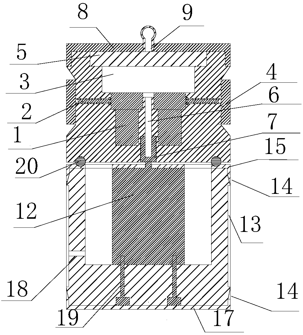
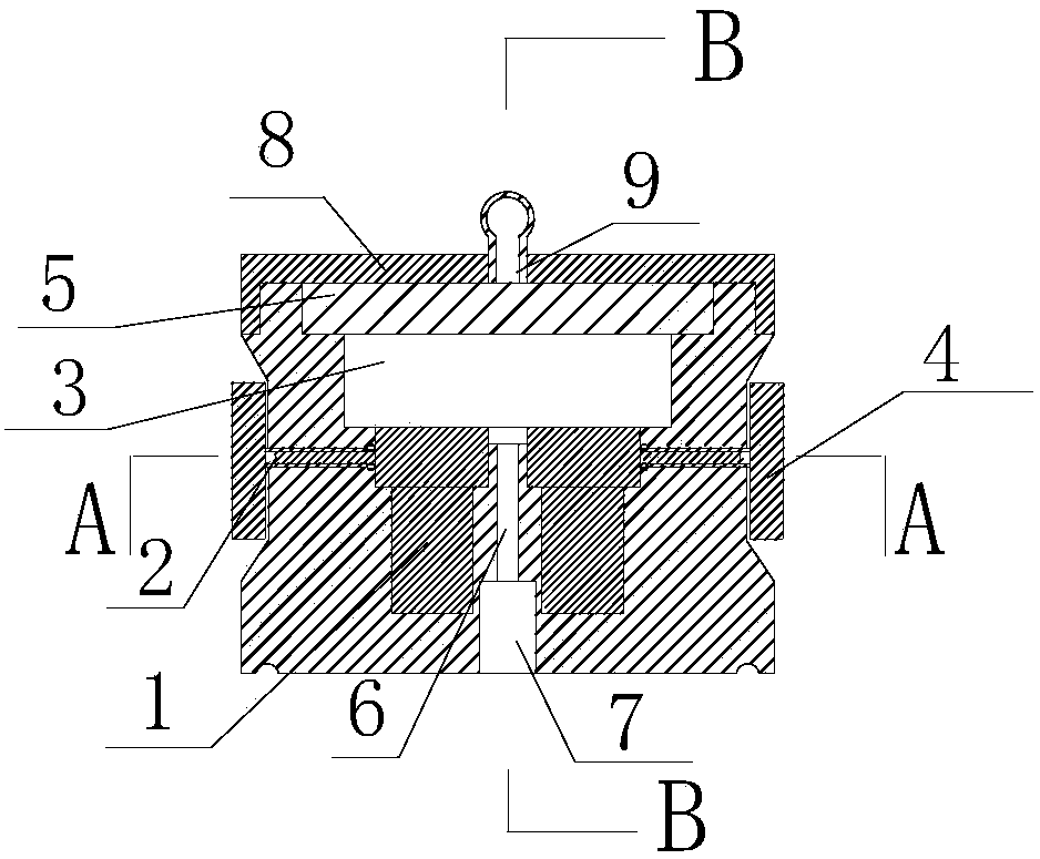
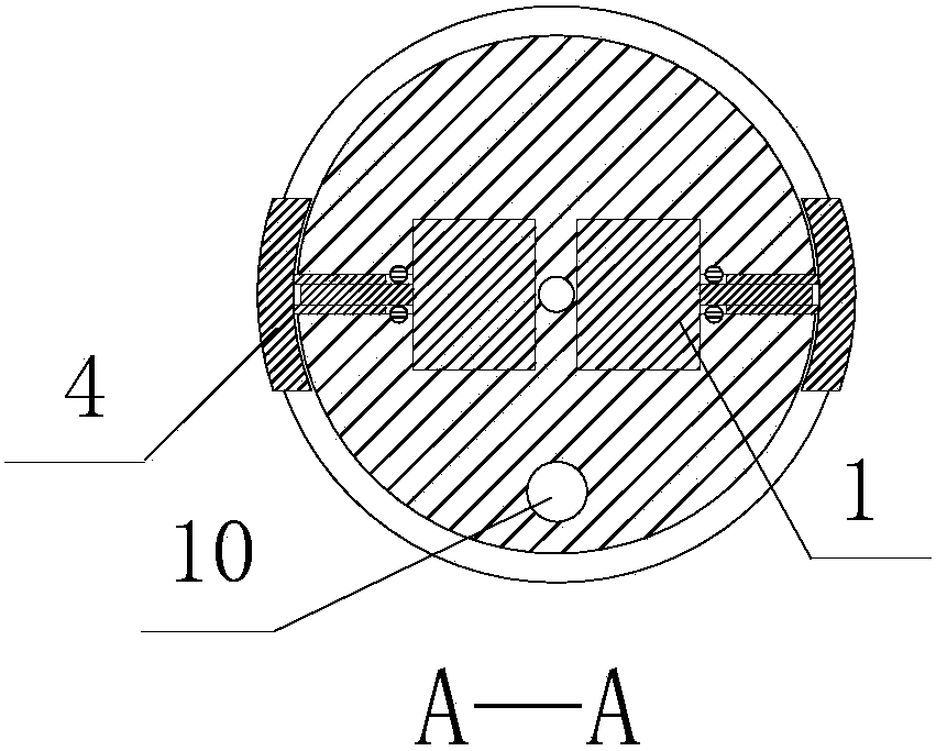
[0028] Such as Figure 2A , Figure 2B , Figure 2C and Figure 3A , Figure 3B , Figure 3C As shown, a direction-controllable in-hole sensor base includes an upper base and a lower base. As shown in Figure 2, the upper base includes a DC turbine worm motor 1 (ASLONG A58SW31ZY), a push rod 2, a sensor nest 3, a support shoe 4, an electronic compass 5 (DCM220B), a screw 6, an upper base cap 8, a lifting ring 9 and a limiter. Bit pile 11. The DC turbine worm motor 1 is fixed on the bottom of the upper base, the sensor nest 3 is fixed on the top of the DC turbine worm motor 1, the sensor is fixed inside the sensor nest 3, the electronic compass 5 is fixed on the top of the sensor nest 3, and the electronic compass 5 The X and Y directions are consist...


PUM


Abstract

The invention discloses a direction controllable sensor base in a hole. The direction controllable sensor base comprises an upper base and a lower base, wherein the upper base comprises a direct-current turbine worm motor, a push rod, a sensor nest, supporting boots, an electronic compass, a screw, an upper base cover cap, a hanging ring and a limiting pile, the direction of the electronic compass is the same as that of the sensor, and the upper base pushes the supporting boots to move towards two sides through the push rod in virtue of the direct-current turbine worm motor; the lower base comprises a direct-current low-speed motor, an air bag, a wedge-shaped cross section circular ring, a lower base upper cover cap and a lower base bottom cover cap, a rotating shaft of the direct-current low-speed motor is inserted in a connecting hole of the upper base and is arranged on the screw in a sleeving manner, the wedge-shaped cross section circular ring is used for fixing the air bag and the upper end and the lower end of the lower base, and the limiting pile of the upper base is inserted in a semi-circular ring-shaped groove in the top of the lower base for rotational connection. The sensor base is used for placing a sensor in a drilling hole, has the functions of hole wall fixation and sensor direction adjustment, is simple in structure and convenient in operation, and is suitable for rock and earth mass dynamic parameter testing among drilling holes.

Description

technical field [0001] The invention belongs to the field of geotechnical engineering testing, and in particular relates to a direction-controllable in-hole sensor base, which is used to place a sensor for measuring dynamic parameters of rock and soil in a borehole. Background technique [0002] The cross-hole method is one of the commonly used methods for geotechnical engineering field testing, and its purpose is to test the dynamic mechanical properties of rock and soil between boreholes. The basic steps of the cross-hole method are: arranging multiple drill holes on a straight line, which are respectively the excitation hole and the test hole, placing the sensor in the test hole, the sensor is fixed on the hole wall, and the stress wave generated by the test excitation hole passes through the drill hole. The vibration information of the inter-soil mass propagation, and then the dynamic parameters of the rock-soil mass, such as wave velocity, dynamic modulus, damping ratio...

Claims


Application Information

Patent Timeline
Patent Type & Authority Patents(China)
IPC IPC(8): E02D1/00
CPCE02D1/00
Inventor 周青春李海波李俊如刘博
Owner INST OF ROCK & SOIL MECHANICS CHINESE ACAD OF SCI
Learn More