Surrounding adjustable mounting point precision sensor vibration damping bracket

A technology of pointing precision and sensors, applied in aerospace vehicles, aircraft, transportation and packaging, etc., can solve problems such as non-structural design, achieve simple structure, achieve precision, and improve the effect of mechanical environment

Active Publication Date: 2018-08-14
BEIJING INST OF SPACECRAFT SYST ENG
View PDF5 Cites 0 Cited by
  • Summary
  • Abstract
  • Description
  • Claims
  • Application Information

AI Technical Summary

Problems solved by technology

[0004] The vibration damping bracket is an important structural form for suppressing and reducing the vibration response of the instrument and equipment installation in the spacecraft assembly design. The existing vibration damping bracket is mainly designed in the form of a damping shock absorber supplemented by an instrument and equipment installation platform. This type of vibration damping bracket It has a good vibration suppression effect for the installation of major equipment. In the design of large-scale deployment antennas in space, the main bearing cylinder of spacecraft and the vibration-damping support of the load-bearing platform, the form of damping shock absorber is mainly used, while for small instruments and equipment , especially the vibration damping support that can provide auxiliary support for the installation of the sensor and has the adjustment and testing of the sensor pointing accuracy, there is no specific structural design at present

Method used


Image

  • Surrounding adjustable mounting point precision sensor vibration damping bracket
  • Surrounding adjustable mounting point precision sensor vibration damping bracket

Examples


Embodiment Construction

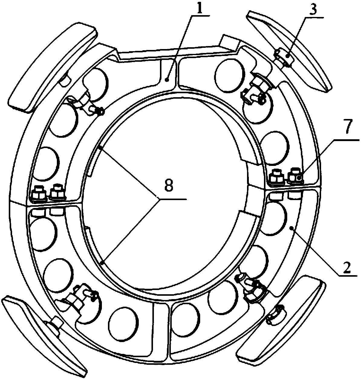
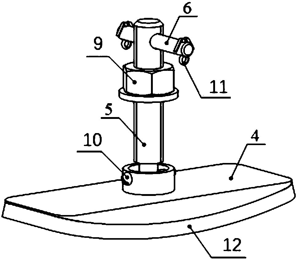
[0015] See attached figure 1 : An embracing type adjustable mounting pointing accuracy sensor vibration damping bracket, which includes: embracing clamps and adjusting support 3;

[0016] The embracing hoop is made of metal material, and a silicone shock absorbing pad A8 is provided on its inner annular surface. The coverage area of ​​the silica gel shock absorbing pad A8 is not less than 85% of the area of ​​the inner annular surface of the embracing hoop, and the thickness is 3mm-5mm; Four threaded holes for installing the adjustment support 3 are evenly distributed on the outer annular surface; a U-shaped groove that provides enough space for the operation inside the encircling clamp is provided on the end surface of one side of the encircling clamp; further, for It can effectively reduce the accuracy requirements of the center of the surrounding clamp on the opening of the sensor end, and facilitate the installation of the auxiliary support of the vibration damping bracket...


PUM


Abstract

The invention belongs to the field of structure design of a spacecraft assembly, and particularly relates to adjusting measurement of pointing accuracy of a spacecraft sensor as well as auxiliary supporting and vibration reduction of end parts. An embraced type sensor vibration reducing bracket with adjustable installing and pointing accuracy comprises an embraced hoop and adjusting supports, wherein each adjusting support comprises an adjusting screw rod, a supporting seat and a falling-preventing screw, the adjusting screw rod is provided with a locking nut, a wrench is arranged at one end of the adjusting screw rod, the other end is installed in a ring groove in the inner end surface of the supporting seat through the falling-preventing screw, a silica gel shock pad B is arranged on the outer end surface of the supporting seat, and the adjusting support is mounted at a threaded hole in the embraced hoop through the adjusting screw rod. According to the invention, the end parts of the sensor are subjected to auxiliary support, the installing form of the sensor is changed from a cantilever form to a simple support form, so that the mechanical environment of the sensor is improved, and the installation stability is improved; the precision adjusting measurement of a pointing shaft of the sensor can be realized at the accurate measurement stage of the spacecraft assembly.

Description

technical field [0001] The invention belongs to the field of spacecraft assembly structure design, and in particular relates to the commissioning of the pointing accuracy of the spacecraft sensor and the auxiliary support and vibration reduction of the end. Background technique [0002] With the development of space science and technology, the requirements for the capability level of spacecraft are getting higher and higher, especially the improvement of the mechanical environment for the installation of instruments and equipment on the spacecraft platform and the ability to maintain the stability of the installation of sensors with high-precision pointing requirements. During the ground test and launch process, the spacecraft will inevitably experience mechanical environments such as vibration, impact and noise. As the basic constraints of the spacecraft assembly structure design, it always restricts the development of the spacecraft platform towards high precision and high ...

Claims


Application Information

Patent Timeline
Patent Type & Authority Patents(China)
IPC IPC(8): B64G1/66
CPCB64G1/66
Inventor 古青波张新星刘欣赵二鑫王晓姝张也弛李昂张龙赵会光李春华
Owner BEIJING INST OF SPACECRAFT SYST ENG
Why Eureka
Try Eureka