Knockout bar connection mechanism of injection molding machine

A technology of connecting mechanism and stripper rod, which is applied in the field of stripping rod connection mechanism, can solve problems such as loose threaded connection, waste of labor and time, mold damage, etc., and achieve the effect of preventing loosening

Inactive Publication Date: 2017-01-25
SINO HLDG GRP
View PDF9 Cites 0 Cited by
  • Summary
  • Abstract
  • Description
  • Claims
  • Application Information

AI Technical Summary

Problems solved by technology

The structure of the current stripping rod connection mechanism is as follows: Figure 5 As shown, including demoulding piston rod 1', demoulding plate 3', demoulding rod 6', movable platen 7' and mold ejector plate 8', this structure is suitable for injection mold with return spring, demoulding rod 6' and When the mold ejector plate 8' does not need to be connected; when the injection mold has no return spring, it will be very difficult when the threaded connection between the ejector rod 6' and the mold ejector plate 8' is required, because one end of the ejector rod 6' It is connected with the mold ejector plate 8' through threads, and the other end is connected with the demoulding piston rod 1' through threads. The threads at both ends must be tightened at the same time with positive and negative threads, or remove the mold and connect the mold ejector plate 8' with the demoulding rod. 6' connection, a waste of labor and time in actual operation, and in use, because the stripping piston rod 1' is not positioned radially, there will be a loose threaded connection between the stripping rod 6' and the stripping piston rod 1', which is serious When the mold is damaged, the economic loss is very large

Method used


Image

  • Knockout bar connection mechanism of injection molding machine
  • Knockout bar connection mechanism of injection molding machine
  • Knockout bar connection mechanism of injection molding machine

Examples


Embodiment Construction

[0014] The specific embodiments of the present invention will be further described below in conjunction with the accompanying drawings.

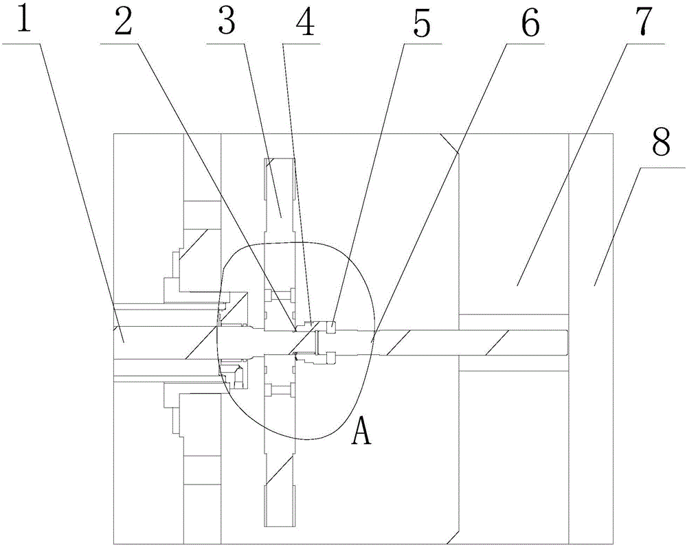
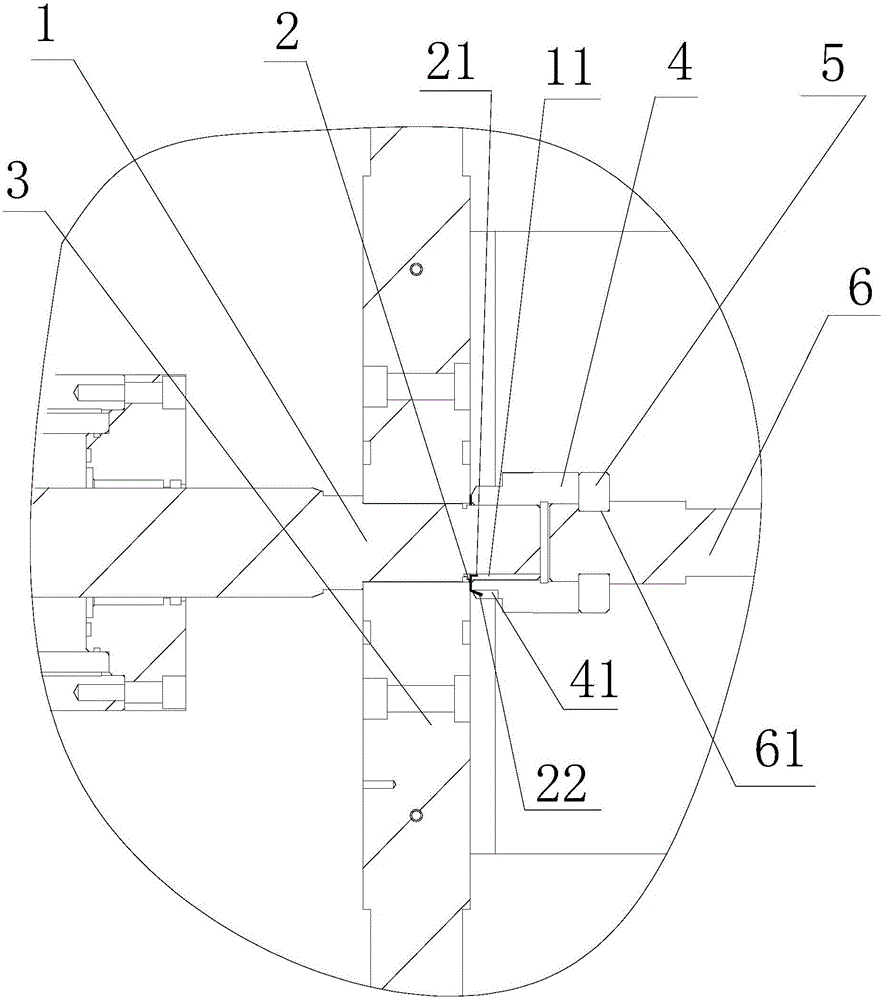
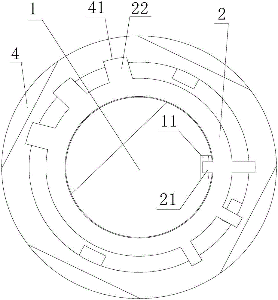
[0015] Such as Figure 1-3 As shown, a stripping rod connection mechanism of an injection molding machine includes a stripping piston rod 1, a stripping plate 3 (also called a ejector plate, used for installing ejector pins), a stripping lever 6, a movable platen 7 and an ejector plate 8 One end of the demoulding rod 6 passes through the movable template 7 and is connected to the ejector plate 8, and the other end of the demolding rod 6 is connected to the demoulding piston rod 1 through the demoulding rod fixing seat 4 , the demoulding rod fixing seat 4 is threadedly connected to the demoulding piston rod 1, and the demoulding rod 6 is formed with an annular groove 61 in the circumferential direction, and a positioning ring is embedded in the annular groove 61 5. The positioning ring 5 is fixedly connected with the demoulding rod fixing se...


PUM


Abstract

The invention discloses a knockout bar connection mechanism of an injection molding machine. The knockout bar connection mechanism comprises a knockout piston rod, a knockout plate, a knockout bar, a moving plate and an ejector plate. One end of the knockout bar penetrates the moving plate to be connected with the ejector plate while the other end of the knockout bar is connected with the knockout piston rod through a knockout bar holder; the knockout bar holder is in threaded connection with the knockout piston rod; the knockout bar is provided with a circular groove circumferentially and a positioning ring is embedded in the circular groove; the positioning ring is fixedly connected with the knockout bar holder through bolts; the end of the knockout piston rod is provided with piston rod key slots radially, and the circumference of the knockout bar holder is provided with holder key slots radially; a locking washer is arranged between the knockout plate and the knockout bar holder and is provided with internal locking teeth and external locking teeth, the internal locking teeth are connected with the piston rod key slots, and the external locking teeth are connected with the holder key slots. The knockout bar connection mechanism has the advantages of convenience in installation and connection and high stability and strength.

Description

technical field [0001] The invention relates to a demoulding mechanism of an injection molding machine, in particular to a connecting mechanism of a demoulding rod of an injection molding machine. Background technique [0002] The demoulding mechanism is a necessary mechanism to realize the demoulding after the product is formed, and it is an important part of the injection molding machine, and the demoulding rod connection mechanism is the core mechanism of the demoulding mechanism. The structure of the current stripping rod connection mechanism is as follows: Figure 5 As shown, including demoulding piston rod 1', demoulding plate 3', demoulding rod 6', movable platen 7' and mold ejector plate 8', this structure is suitable for injection mold with return spring, demoulding rod 6' and When the mold ejector plate 8' does not need to be connected; when the injection mold has no return spring, it will be very difficult when the threaded connection between the ejector rod 6' an...

Claims


Application Information

Patent Timeline
IPC IPC(8): B29C45/40
CPCB29C45/401
Inventor 李君
Owner SINO HLDG GRP
Why Eureka
Try Eureka