Automated punching equipment

A technology of stamping equipment and stamping components, applied in the field of automatic stamping equipment, can solve problems affecting stamping accuracy, bending deformation, etc.

Active Publication Date: 2017-01-25
珠海市金质精密科技有限公司
View PDF6 Cites 4 Cited by
  • Summary
  • Abstract
  • Description
  • Claims
  • Application Information

AI Technical Summary

Problems solved by technology

However, this kind of stamping equipment only relies on the punch to apply force to the part to be stamped in one direction, which is likely to cause the whole part to be stamped to be bent and deformed to one side, thereby affecting the stamping accuracy

Method used


Image

  • Automated punching equipment
  • Automated punching equipment
  • Automated punching equipment

Examples


Embodiment Construction

[0021] In order to make the above objects, features and advantages of the present invention more comprehensible, specific implementations of the present invention will be described in detail below in conjunction with the accompanying drawings. In the following description, numerous specific details are set forth in order to provide a thorough understanding of the present invention. However, the present invention can be implemented in many other ways different from those described here, and those skilled in the art can make similar improvements without departing from the connotation of the present invention, so the present invention is not limited by the specific implementations disclosed below.

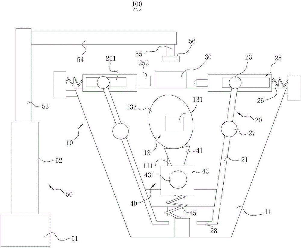
[0022] The invention relates to an automatic stamping equipment. The automatic punching equipment includes a punching device and a manipulator arranged adjacent to the punching device, the punching device includes a machine table, a driving assembly, two oppositely arranged punching a...


PUM


Abstract

The invention relates to automated punching equipment. The automated punching equipment comprises a punching device and a manipulator, wherein the punching device comprises a machine table, a driving assembly, two oppositely-arranged punching assemblies and a locating frame. A connecting assembly is arranged between the two punching assemblies and comprises an abutting member, a sliding member and a compression spring, the two ends of the sliding member are separately connected with the abutting member and the compression spring, the driving assembly is abutted against the abutting member, and the two sides of the sliding member are separately abutted against the two punching assemblies. According to the automated punching equipment, the accuracy of punching is relatively high, and the driving efficiency of the driving assembly is relatively high.

Description

technical field [0001] The invention relates to an automatic stamping equipment. Background technique [0002] With the development of China's economy, the industry has been fully developed. For example, various automobile manufacturers are born out of operations. Some parts on the car need to be punched with stamping equipment. Stamping equipment generally includes a punch and a mold opposite to the punch, and a stamping cavity is formed on the mold. When stamping is required, generally the workpiece to be stamped is first positioned on the mold, and then a punch is used to move toward the mold and pass through the workpiece to be stamped into the stamping cavity. The piece to be stamped is stamped by the punch to form a punching groove. However, this kind of stamping equipment only relies on the punch to exert a unidirectional force on the piece to be stamped, which is likely to cause the entire piece to be stamped to be bent and deformed to one side, thereby affecting...

Claims


Application Information

Patent Timeline
Patent Type & Authority Applications(China)
IPC IPC(8): B21D28/02B21D28/04
CPCB21D28/02B21D28/04
Inventor 章魁
Owner 珠海市金质精密科技有限公司
Why Eureka
Try Eureka