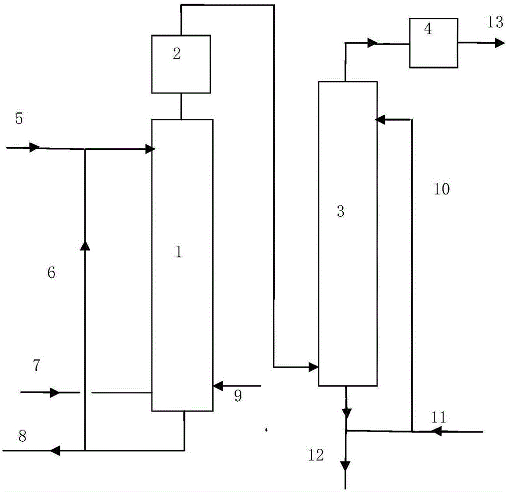
Ultralow emission process for catalytic cracking smoke

A catalytic cracking and flue gas technology, applied in gas treatment, air quality improvement, chemical instruments and methods, etc., can solve problems such as low sulfur resistance, poor adaptability of raw materials, instability, etc., to reduce the generation of pollutants, reduce Effects of purification cost and denitrification cost reduction

Inactive Publication Date: 2017-01-25
SINOPEC ENG GRP CO LTD
View PDF5 Cites 3 Cited by
  • Summary
  • Abstract
  • Description
  • Claims
  • Application Information

AI Technical Summary

Problems solved by technology

SCR denitrification technology has been successfully applied to flue gas denitrification of catalytic cracking units, but the problem of low sulfur resistance of low-temperature SCR catalysts has not been solved, so medium-temperature SCR technology is currently used for flue gas denitrification of catalytic cracking units
The catalytic cracking unit designed in the 20th century basically did not reserve the position of the flue gas denitrification unit, and the flue gas temperature at the outlet of the waste heat boiler of the catalytic cracking unit is generally 180-230 ° C. It is necessary to put the denitrification part into the catalytic waste heat boiler, which increases the engineering implementation. Difficulty, which has a great influence on the structure of the catalytic waste heat boiler
However, the desulfurization and denitrification efficiency of the auxiliary method is low, unstable, poor adaptability to raw materials, and the SOx and NOx contents in the catalytic flue gas are difficult to meet the emission standards at the same time. , NOx emission standards at the same time become more difficult to achieve

Method used


Image

  • Ultralow emission process for catalytic cracking smoke

Examples


Embodiment 1

[0040] The first step: auxiliary desulfurization and denitrification

[0041] The content of NOx and SOx in the flue gas of a refinery catalytic cracking flue gas before adding additives is 1360mg / m 3 , 200mg / m 3 , adding a denitrification additive (LDN-1 denitrification additive) accounting for 1.5% of the total storage capacity of the catalytic cracking catalyst, and after the operation is stable, it is calibrated, and the NOx and SOx contents in the catalytic cracking flue gas are respectively 340mg / m 3 , 180mg / m 3 , The denitrification rate is 75%.

[0042] The second step: desulfurization

[0043] The flue gas from the waste heat boiler of the FCC unit is in full contact with the circulating slurry in the quenching scrubber, and the pH of the circulating slurry is controlled to be 5-9 by adding fresh sodium lye. The quenching scrubber is an empty tower. The concentration of sulfur dioxide in the purified flue gas is 30mg / m 3 , The desulfurization rate is 83.3%.

[...

Embodiment 2

[0047] The first step: auxiliary desulfurization and denitrification

[0048] The content of NOx and SOx in the flue gas of a refinery catalytic cracking flue gas before adding additives is 100mg / m 3 、1115mg / m 3 , adding a desulfurization aid (LST-1 desulfurization aid) accounting for 4% of the total storage capacity of the catalytic cracking catalyst, and then calibrated after the operation is stable. The NOx and SOx contents in the flue gas from catalytic cracking are respectively 95mg / m 3 , 245mg / m 3 , the desulfurization rate is 78%.

[0049] The second step: desulfurization

[0050] The high-temperature flue gas from the waste heat boiler of the FCC unit is in full contact with the circulating slurry in the quenching scrubber, and the pH of the circulating slurry is controlled to be 5-9 by adding fresh sodium lye. The quenching scrubber is an empty tower. The concentration of sulfur dioxide in the purified flue gas is 29.5mg / m 3 , The desulfurization rate is 88%.

...

Embodiment 3

[0054] The first step: auxiliary desulfurization and denitrification

[0055] The content of NOx and SOx in the flue gas of a refinery catalytic cracking flue gas before adding additives is 260mg / m 3 、935mg / m 3 , adding a multi-effect additive (LTA-1 multi-effect additive) accounting for 2.5% of the total storage capacity of the catalytic cracking catalyst, calibrated after the operation was stable, and the NOx and SOx contents in the catalytic cracking flue gas were 158mg / m 3 , 290mg / m 3 , The denitrification rate is 39.2%, and the desulfurization rate is 68.9%.

[0056] The second step: desulfurization

[0057] The flue gas from the waste heat boiler of the FCC unit is in full contact with the circulating slurry in the quenching scrubber, and the pH of the circulating slurry is controlled to be 5-9 by adding fresh sodium lye. The quenching scrubber is an empty tower. The concentration of sulfur dioxide in the purified flue gas is 42mg / m 3 , The desulfurization rate is ...


PUM


Abstract

The invention provides an ultralow emission process for catalytic cracking smoke, comprising the following steps of: introducing an addition agent in a catalytic cracking catalyst, reducing Sox and NOx content in the catalytic smoke in a lower cost maximally, wherein the maximum concentration of NOx in the smoke does not exceed 400mg / m3; high temperature flue gas from a heat recovery boiler of a catalytic cracking device contacts with a circulation slurry in an urgent cooling desulfurizing tower to cool, dedust and desulfurize; the maximum concentration of the desulfurized smoke Sox does not exceed 150mg / m3; the desulfurized smoke enters the bottom ofa denitrating tower by a dustproof defroster to be in reverse contact with a denitrating solution; the denitrated smoke is evacuated after being removal of the fog; Soxin the smoke basically realizes zero emission; and when NOx content is below 30mg / Nm3, the purpose of ultralow emission is realized.

Description

technical field [0001] The invention relates to the technical field of chemical industry, in particular to a catalytic cracking flue gas ultra-low emission process. Background technique [0002] FCC (catalytic cracking) unit is one of the largest sources of pollutant emissions in refineries. In order to meet the requirements of environmental protection control indicators and emission reduction targets, the emissions of SOx and NOx from catalytic cracking flue gas must be strictly controlled. At present, the main method for refineries to control the emission of harmful gases such as SOx and NOx in catalytic cracking flue gas is flue gas purification. FCC flue gas desulfurization technologies that have been industrialized in China include sodium-alkali desulfurization, renewable wet flue gas desulfurization, and denitrification technologies include SCR denitrification and ozone oxidation absorption denitrification. [0003] Sodium-alkali desulfurization is currently the most ...

Claims


Application Information

Patent Timeline
Patent Type & Authority Applications(China)
IPC IPC(8): B01D53/75B01D53/81B01D53/78B01D53/18B01D53/60
CPCB01D53/18B01D53/60B01D53/75B01D53/78B01D53/81B01D2251/108B01D2251/50B01D2251/604B01D2251/304B01D2258/0283Y02A50/20
Inventor 涂先红陈卫红裴旭东李朝恒郭荣群张凡郭玉涛叶春波
Owner SINOPEC ENG GRP CO LTD
Why Eureka
Try Eureka