
Rotary desulfurization and denitrification reactor and system

A desulfurization and denitrification, rotary technology, applied in chemical instruments and methods, separation methods, gas treatment and other directions, can solve the problems of large amount of waste residue, large area of ​​reaction device, complex system, etc., and achieve high desulfurization rate and denitrification rate. , The effect of improving the destocking efficiency and the high desulfurization and denitrification rate

Active Publication Date: 2017-01-25
SHANDONG UNIV
View PDF2 Cites 8 Cited by
  • Summary
  • Abstract
  • Description
  • Claims
  • Application Information

AI Technical Summary

Problems solved by technology

SO 2 Control technologies include dry desulfurization and wet desulfurization, etc., which are subdivided into various methods, but the limestone method is the most widely used tail flue gas desulfurization technology. large
Currently NO X and SO 2 Stationary source pollutant control technology is the combination of NOx control and SO 2 The control is carried out separately, which will lead to problems such as large area occupied by the flue gas purification control system, complex system, large initial investment, high operating cost, and high energy consumption, and the traditional NH 3 -SCR denitrification catalyst requires a narrow flue gas temperature window, which restricts the application of flue gas desulfurization and denitrification technology
[0003] for NO X and SO 2 Control technology Disadvantages of separate control technologies, absorption desulfurization and denitrification technology can remove NO at the same time X and SO 2 The characteristics of NO have attracted widespread attention. Most of the existing absorption desulfurization and denitrification technologies use activated carbon and other adsorbents with strong adsorption capacity to adsorb NO. X with SO 2 , so as to achieve NO X with SO 2 The purpose of emission reduction, but it is necessary to take out the activated carbon and other adsorbent materials for regeneration, and the regenerated reducing gas is directly discharged. On the one hand, it causes waste of reducing gas, and on the other hand, the discharged reducing gas is doped with NO X , this part of nitrogen oxides is difficult to deal with and pollutes the environment
At the same time, this method also has problems such as a large area of ​​the reaction device, a large amount of adsorbent used, and difficulty in continuous production.

Method used


Image

  • Rotary desulfurization and denitrification reactor and system
  • Rotary desulfurization and denitrification reactor and system
  • Rotary desulfurization and denitrification reactor and system

Examples


Embodiment 1

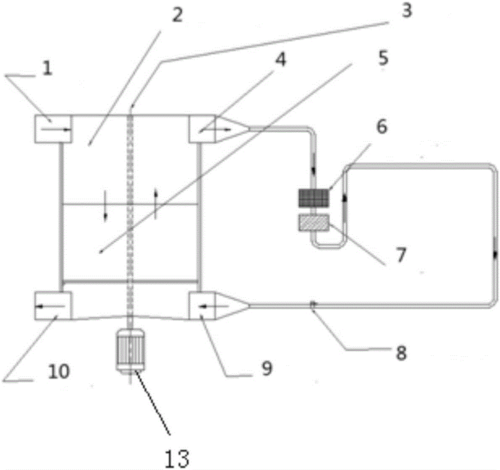
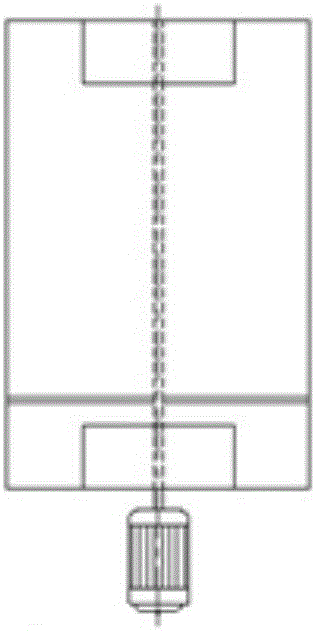
[0043] Such as figure 1 As shown, a rotary desulfurization and denitrification reactor includes a cylindrical shell 12, a rotating shaft 3 and a partition 11, the rotating shaft 3 is installed inside the cylindrical casing 12, and the partition 11 is fixedly installed on the rotating shaft 3, and the The cylindrical housing 12 is divided into at least two chambers, and the chamber is filled with catalyst, SO 2 The adsorbent 11 is located above the nitrogen oxide catalyst 5, and the rotating shaft 3 rotates under the drive of the motor 13; the top of the cylindrical shell 12 is provided with a flue gas inlet 1 and a reducing gas outlet 4, and the flue gas inlet 1 and the reducing gas outlet 4 Oppositely, the bottom of the cylindrical housing 12 is provided with a flue gas outlet 10 and a reducing gas inlet 9 , the flue gas outlet 10 is located below the flue gas inlet 1 , and the reducing gas inlet 9 is located below the reducing gas outlet 4 . The flue gas inlet 1, the flue g...

Embodiment 2

[0054] A rotary desulfurization and denitrification reactor, comprising a cylindrical shell 12, a rotating shaft 3 and a partition 11, the rotating shaft 3 is installed inside the cylindrical shell 12, the partition 11 is fixedly installed on the rotating shaft 3, and the cylindrical shell 12 separated into at least two chambers filled with catalyst, SO 2 The adsorbent 2 is located above and below the nitrogen oxide catalyst 5, and the rotating shaft 3 rotates under the drive of the motor 13; the bottom of the cylindrical shell 12 is provided with a flue gas inlet 1 and a reducing gas outlet 4, and the flue gas inlet 1 and the reducing gas outlet 4 Oppositely, the top of the cylindrical shell 12 is provided with a flue gas outlet 10 and a reducing gas inlet 9 , the flue gas outlet 10 is located above the flue gas inlet 1 , and the reducing gas inlet 9 is located above the reducing gas outlet 4 .


PUM


Abstract

The invention discloses a rotary desulfurization and denitrification reactor and a system. The reactor comprises a columnar shell, a rotary shaft and a clapboard, wherein the rotary shaft is mounted in the columnar shell, the clapboard is fixedly arranged on the rotary shaft to divide the columnar shell into at least two chambers, the chambers are filled with catalysts, an SO2 adsorbent is positioned above the nitrogen oxide catalyst, and the rotary shaft rotates under the driving of a motor; a smoke inlet and a reduction gas outlet are formed at the top of the columnar shell, the smoke inlet is arranged opposite to the reduction gas outlet, a smoke outlet and a reduction gas inlet are formed in the bottom of the columnar shell, the smoke outlet is positioned below the smoke inlet, and the reduction gas inlet is positioned below the reduction gas outlet. The two catalysts are overlapped vertically, and smoke flow from top to bottom, so as to realize simultaneous adsorption of SO2 and nitrogen oxide. due to adoption of the rotary reactor, the reduction gas flows from top to bottom, desorption and reaction of SO2 and nitrogen oxide are realized.

Description

technical field [0001] The invention belongs to the field of environmental protection, and relates to flue gas desulfurization and denitrification, in particular to a rotary desulfurization and denitrification reactor and system. Background technique [0002] NO X and SO 2 It is the main gaseous pollutant in the current air pollutants, and its massive discharge has caused great harm to the human body and the environment. With the increasing pressure of environmental protection, NO X and SO 2 emissions are subject to increasingly stringent restrictions. Coal-fired power stations and smelters are the main NO X and SO 2 Emissions from stationary sources which contribute to NO X and SO 2 The control level directly affects atmospheric NO X and SO 2 content. NO X Control technology is divided into SNCR technology, SCR technology and other technologies, among which SCR method is currently the most effective tail NO X removal technique. SO 2 Control technologies inclu...

Claims


Application Information

Patent Timeline
IPC IPC(8): B01D53/06
CPCB01D53/06B01D2257/302B01D2257/404B01D2259/40083
Inventor 程星星王志强张铭马春元董勇
Owner SHANDONG UNIV
Learn More