A spring-type automatic spraying one-piece nozzle

An automatic spraying and spring-type technology, applied in the direction of the spraying device, can solve the problems of inconvenient operation, laborious, low efficiency, etc., and achieve the effect of efficient spraying operation

Active Publication Date: 2019-10-01
广东自由能科技股份有限公司
View PDF6 Cites 0 Cited by
  • Summary
  • Abstract
  • Description
  • Claims
  • Application Information

AI Technical Summary

Problems solved by technology

The manual nozzle spraying method is labor-intensive for the operator, and the nozzle needs to be pressed all the time to achieve continuous spraying, which is not efficient; the special spray gun is expensive and inconvenient to operate

Method used


Image

  • A spring-type automatic spraying one-piece nozzle
  • A spring-type automatic spraying one-piece nozzle
  • A spring-type automatic spraying one-piece nozzle

Examples


Embodiment 1

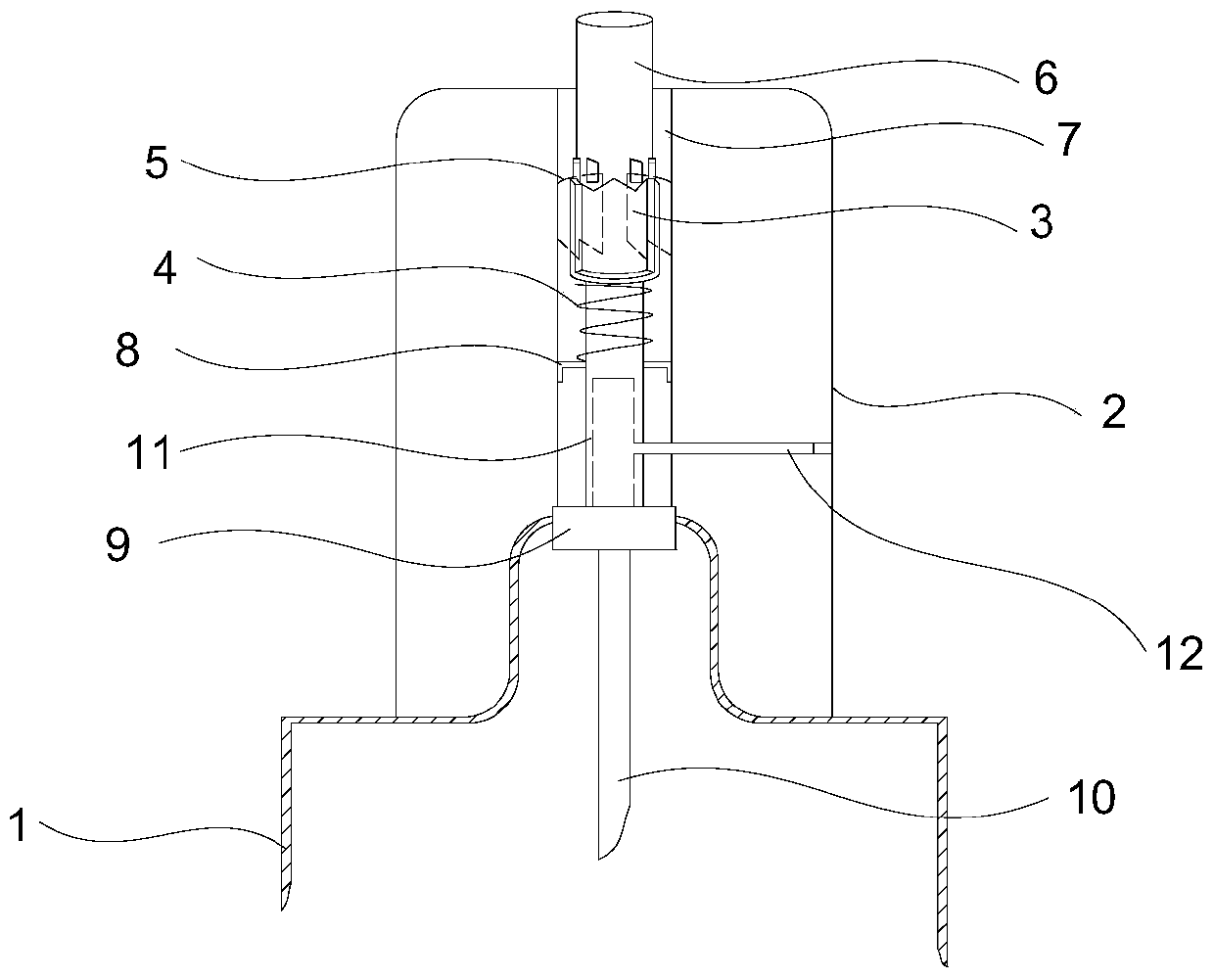
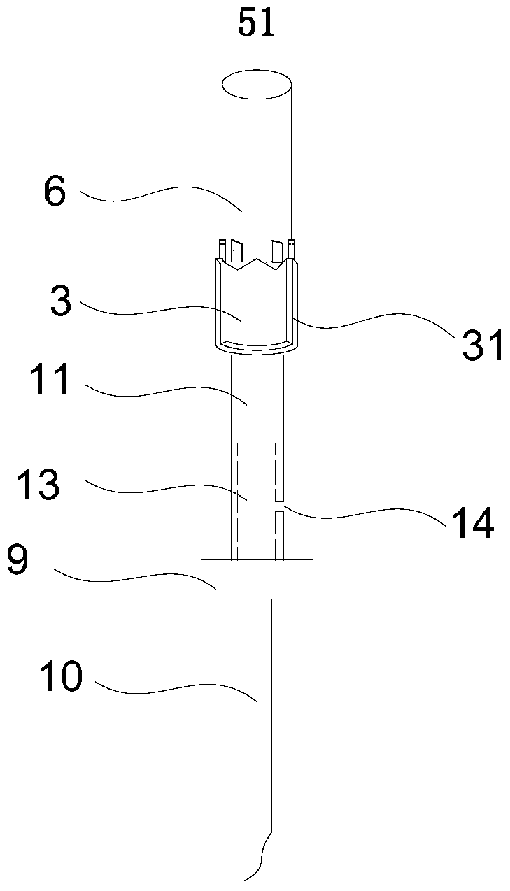
[0014] like Figure 1-3 As shown, the spring type automatic spraying one-piece nozzle includes a valve cover 2, an aerosol valve and a telescopic mechanism.

[0015] The aerosol valve includes a valve chamber 9 , a liquid introduction pipe 10 and a valve stem 11 , and the liquid introduction pipe 10 and the valve stem 11 are located on opposite sides of the valve chamber 9 . The valve chamber 9 is fixed on the filling mouth of the aerosol can 1 , one end of the liquid introduction pipe 10 is connected to the valve chamber, and the other end is connected to the inside of the aerosol can 1 . The valve stem 11 is connected to the valve chamber 9 and has a cavity 13 inside, and the cavity 13 communicates with the valve chamber 9; the valve stem 11 is provided with a discharge port 14 communicating with the cavity 13 . Compress the valve stem 11, the valve in the valve chamber 9 opens, the aerosol in the aerosol can 1 can enter the cavity 13 of the valve stem 11 through the liquid...

Embodiment 2

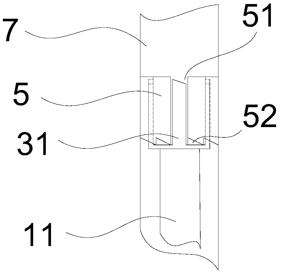
[0020] The difference between this embodiment and the spring-type automatic spraying one-piece spray head of Embodiment 1 is that the rear end of the indexing drum 3 is integrally connected with the end of the valve stem 11; The telescoping groove sleeve 5 forms deep grooves 51 and shallow grooves 52 that are staggered between the corresponding indexing claws 31, but directly forms deep grooves 51 and shallow grooves that are staggered between the corresponding indexing claws 31 on the inner wall of the accommodating channel 7 52. Other structures are the same as in Embodiment 1.

[0021] The spring-type automatic spraying one-piece nozzle of the present invention uses the spring and the ejector pin type mechanical telescopic structure to provide the driving force to drive the valve stem to achieve the cycle function of automatic spraying when pressed and automatic stop when pressed again, so that the hand-sprayed aerosol spraying can achieve automatic spraying. The effect of ...


PUM


Abstract

The invention discloses a spring-type automatic spraying conjoined nozzle, and relates to the technical field of atomizing. The nozzle comprises an aerosol valve and a valve bonnet. The valve bonnet is provided with a containing channel. A telescoping mechanism is arranged in the containing channel. The telescoping mechanism comprises a sliding paw sleeve, an indexing drum and a spring. Matched sliding paws are arranged at the rear end of the sliding paw sleeve and the front end of the indexing drum. Indexing paws are arranged on the outer wall of the indexing drum. Deep grooves and shallow grooves are formed in the inner wall of the containing channel and correspond to the gap between the indexing paws, and the two sorts of grooves are arrayed in a staggered mode. The rear end of the indexing drum is connected with a valve rod of the aerosol valve. The spring is located between the rear end of the indexing drum and a valve chamber. According to the spring-type automatic spraying conjoined nozzle, the spring-lifting pin type mechanical telescoping structure is adopted for providing driving force, the valve rod can be driven to achieve the circulatory function that automatic spraying can be realized when being pressed and spraying can be stopped automatically when being pressed again, the effects of automatic spraying and automatic spraying stopping are achieved when aerosol is sprayed manually, and thus simple, labor-saving and efficient spraying operation can be realized.

Description

technical field [0001] The invention relates to the technical field of spraying, in particular to a spring-type automatic spraying one-piece nozzle. Background technique [0002] At present, the aerosol cans for automatic aerosol spraying generally adopt two methods of spraying with a hand-pressed spray nozzle or spraying with a special spray gun. The manual nozzle spraying method is laborious for the operator, and the nozzle needs to be pressed all the time to achieve continuous spraying, which is not efficient; the special spray gun is expensive and inconvenient to operate. Therefore, it is necessary to propose a spray can that can not only achieve automatic spraying, but also be simple, labor-saving and efficient for operators. Contents of the invention [0003] In order to solve the above problems, realize the automatic spraying and automatic stop of the spraying head, achieve the purpose of simple, labor-saving and efficient operators, and promote the development of ...

Claims


Application Information

Patent Timeline
Patent Type & Authority Patents(China)
IPC IPC(8): B05B12/00
Inventor 杨青坡张代兵
Owner 广东自由能科技股份有限公司
Why Eureka
Try Eureka