Eureka AIR delivers breakthrough ideas for toughest innovation challenges, trusted by R&D personnel around the world.

Automatic mode-locked fiber laser and application thereof

A fiber laser and automatic mode-locking technology, which is applied to lasers, laser components, phonon exciters, etc., can solve the problems of expensive, unsatisfactory simplicity, cheapness, miniaturization, etc., and achieve easy implementation, simple and efficient implementation, and improved work efficiency and

Active Publication Date: 2017-01-11
SHANDONG UNIV
View PDF3 Cites 2 Cited by
  • Summary
  • Abstract
  • Description
  • Claims
  • Application Information

AI Technical Summary

Problems solved by technology

In 2013, Daba Radnatarov et al. used the RF spectrum of the output laser to determine whether it was in a mode-locked state by judging the signal-to-noise ratio, but it needed the assistance of an RF spectrometer (Daba Radnatarov et al, Optics Express 21, 20626-20631, 2013)
[0007] The above-mentioned automatic mode-locking methods either use expensive instruments and equipment, or have certain restrictions, and cannot meet the needs of simplicity, cheapness, and miniaturization

Method used


Image

  • Automatic mode-locked fiber laser and application thereof
  • Automatic mode-locked fiber laser and application thereof
  • Automatic mode-locked fiber laser and application thereof

Examples


Embodiment 1

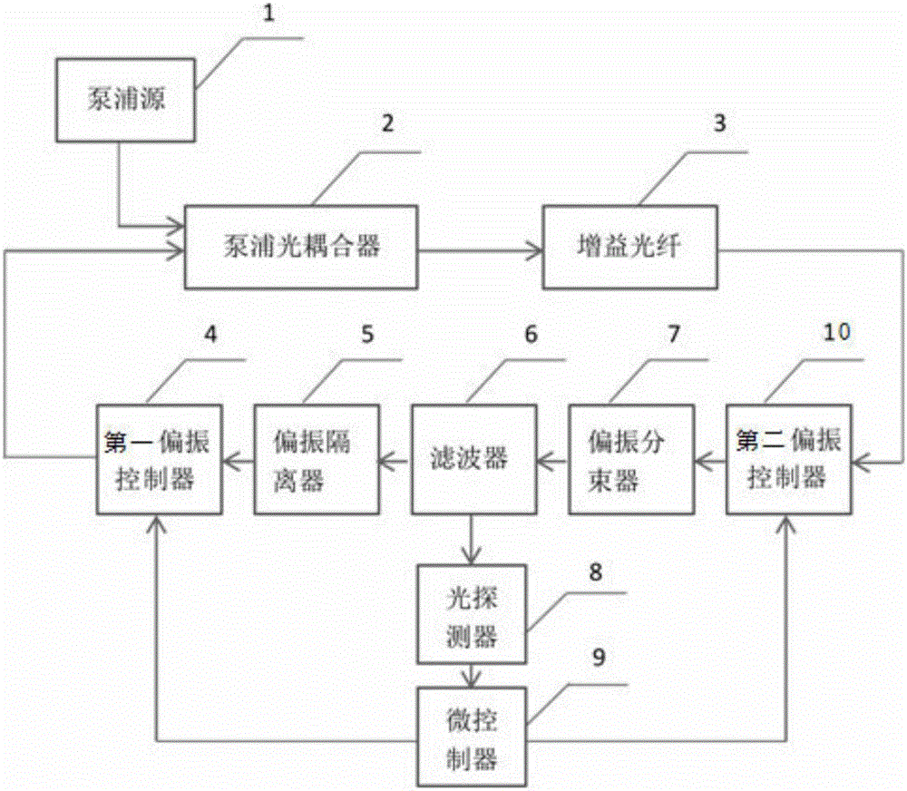
[0037] like figure 1 shown.

[0038] An automatic mode-locked fiber laser, including a fiber laser and an automatic mode-locked control module; the fiber laser includes a pumping source 1 and a resonant cavity; the resonant cavity includes a pumping optical coupler 2, a gain An optical fiber 3, a first polarization controller 4, a polarization beam splitter 7, a filter 6, a polarization isolator 5 and a second polarization controller 10; the automatic mode-locking control module includes an optical detector 8 and a microcontroller 9; The filter 6 is connected to a microcontroller 9 through a photodetector 8 . The photodetector 8 is used to detect the laser output from the filter 6, and the microcontroller 9 counts and detects the signal level of the photodetector 8 so as to judge the current working state of the laser, and simultaneously according to the current state of the fiber laser The state automatically adjusts the polarization controller to obtain the function of aut...

Embodiment 2

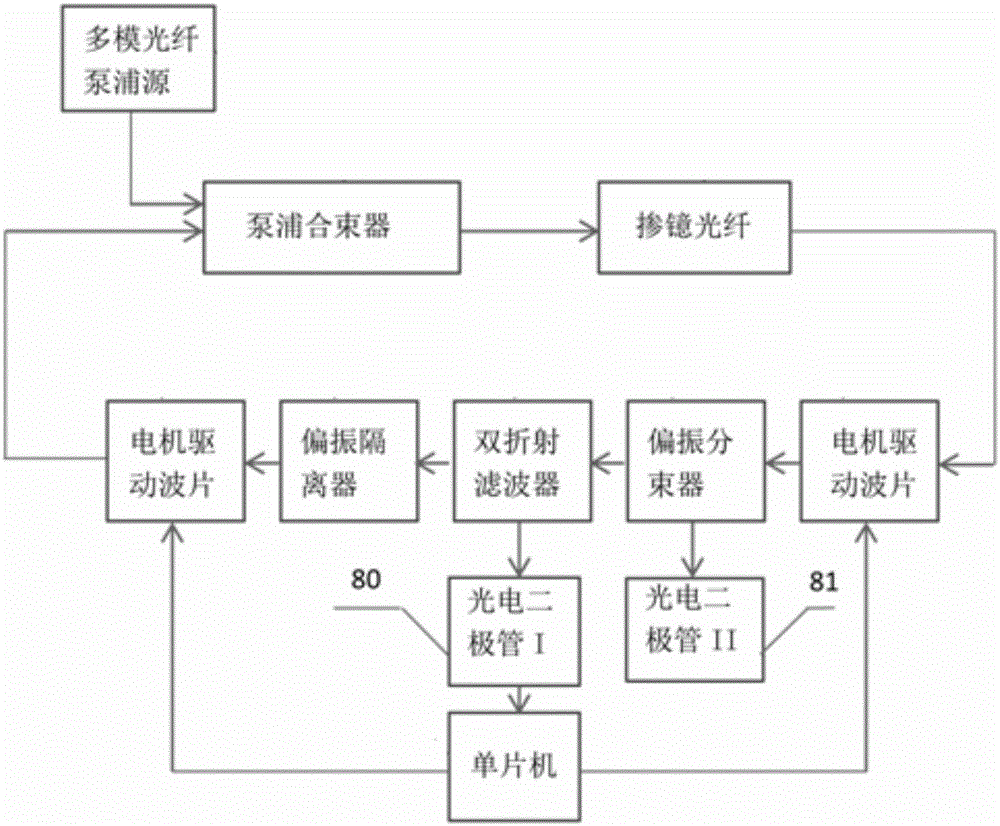
[0040] As in the automatic mode-locked fiber laser described in Embodiment 1, the difference is that the pumping source 1 is a multimode fiber semiconductor laser.

Embodiment 3

[0042] As in the automatic mode-locked fiber laser described in Embodiment 1, the difference is that the pump optical coupler 2 is a pump beam combiner with a fiber structure.


PUM


Abstract

The invention relates to an automatic mode-locked fiber laser and application thereof. The laser comprises a fiber laser body and an automatic mode-locked control module; the fiber laser body comprises a pumping source and a resonant cavity; the resonant cavity comprises a pumping optical coupler, a gain fiber, a first polarization controller, a polarization beam splitter, a filter, a polarization isolator and a second polarization controller; the automatic mode-locked control module comprises an optical detector and a microcontroller; the filter is connected with the microcontroller through the optical detector.

Description

technical field [0001] The invention relates to an automatic mode-locking fiber laser and its application, and belongs to the technical field of automatic mode-locking control of fiber lasers. Background technique [0002] Fiber laser has the advantages of smaller size, stronger heat dissipation energy, more convenient thermal management, higher reliability and stability, etc., so it has been extensively researched and developed, and has important roles in supercontinuum generation, industrial processing, communication and other fields. role. In recent years, the pulse energy of passively mode-locked fiber lasers has been continuously improved, and has been comparable to that of solid-state lasers. [0003] The pulse formation mechanism of passively mode-locked fiber lasers has also evolved from traditional soliton pulses to dispersion-managed solitons, self-similar pulses, and dissipative solitons. Among them, dissipative solitons have high pulse energy, large pulse chirp...

Claims


Application Information

Patent Timeline
IPC IPC(8): H01S3/098H01S3/067
CPCH01S3/06716H01S3/1109
Inventor 卓壮王云征郭松振魏东田桂霞
Owner SHANDONG UNIV
Why Eureka
Eureka Blog
Learn More