
A two-stage temperature control device for a pump-driven two-phase fluid circuit

A temperature control device and fluid circuit technology, applied in the direction of temperature control, temperature control, non-electric variable control, etc., using electric methods, can solve the problems of difficult temperature control, large energy consumption, uneven heating, etc., and achieve response time Short, energy-saving, fast-response effects

Active Publication Date: 2018-04-10
BEIJING INST OF SPACECRAFT SYST ENG
View PDF7 Cites 0 Cited by
  • Summary
  • Abstract
  • Description
  • Claims
  • Application Information

AI Technical Summary

Problems solved by technology

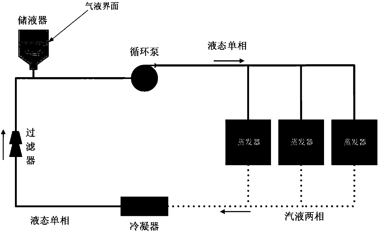
However, when the scale of the pump-driven two-phase fluid system is relatively large, especially when the temperature range is relatively wide, the volume of the working fluid in the reservoir caused by the change of high and low temperature of the system will change greatly, and the liquid level will fluctuate continuously. A relatively large liquid reservoir is used to meet the needs of large-scale system temperature changes. At this time, due to the increase in the volume of the liquid reservoir, there is a problem of uneven heating in it, and the change of the liquid level in the liquid reservoir can accurately control the temperature of the system. Difficult and energy-intensive to control

Method used


Image

  • A two-stage temperature control device for a pump-driven two-phase fluid circuit
  • A two-stage temperature control device for a pump-driven two-phase fluid circuit

Examples


Embodiment Construction

[0018] The present invention will be described in detail below with reference to the accompanying drawings and examples.

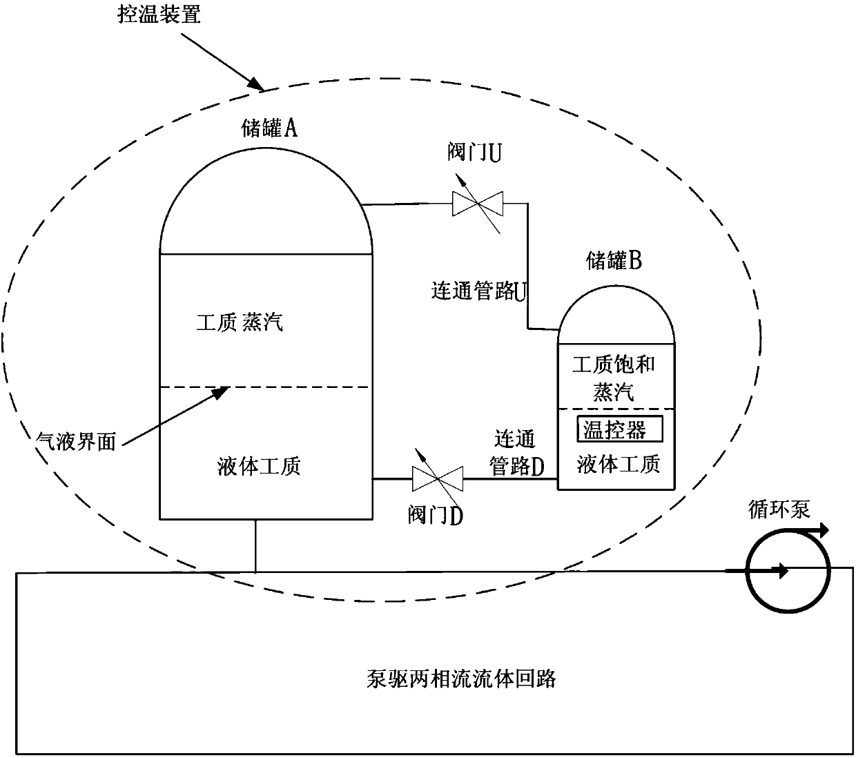
[0019] The invention provides a two-stage temperature control device for a pump-driven two-phase fluid circuit, which separates the two functions of the temperature control of the original liquid reservoir in the pump-driven two-phase fluid circuit system and the compensation for the high and low temperature volume changes of the working medium, and realizes the Accurate control of system temperature.

[0020] The two-stage temperature control device used in the pump-driven two-phase fluid circuit is a liquid reservoir, which includes a large storage tank and a small storage tank, as well as associated pipelines and valves. The working quality in the large storage tank is determined by the volume of the two-phase circuit in the pump-driven two-phase fluid circuit system and the operating temperature range of the system. The volume of the large storage tank...


PUM


Abstract

The invention provides a two-stage temperature control device for a pump-driven two-phase fluid loop according to technological difficulties in temperature precise control of a large-scale pump-driven two-phase fluid loop. Temperature control of original liquid reservoirs and high and low-temperature volume change compensation of working mediums in a pump-driven two-phase fluid loop system are separated, and accurate control on the temperature of the system can be realized. According to the device of the invention, temperature control of the original liquid reservoirs and high and low-temperature volume change compensation of the working mediums in the pump-driven two-phase fluid loop system are separated; a large storage tank with a large volume is mainly used for providing a larger space, the volume change of the working medium caused by the temperature change of the system is allowed; a small storage tank with a small volume is used for temperature control, and the liquid level of the working medium in the small storage tank does not change with the temperature of the system; since the volume of the small storage tank is small, the temperature uniformity of the small storage tank is good, and higher control accuracy can be achieved for the system; since only the temperature of the working medium in the small storage tank is controlled, power required by temperature control is small, energy can be saved; and temperature change reaction after temperature control is quick, and response time is short.

Description

technical field [0001] The invention belongs to the technical field of thermal control, and in particular relates to a two-stage temperature control device for a pump-driven two-phase fluid circuit. Background technique [0002] With the development of the Internet and information technology, the demand for large-scale data storage and data processing is increasing, and higher requirements are placed on the computing speed and performance of servers in data centers, and temperature control has become a key factor restricting its development. . [0003] The first-generation data center adopts air cooling, and the power of a single cabinet is generally 3-4kW. The second generation adopts a combination of water cooling and air cooling, and the power of the cabinet can reach 30kW. It is difficult to achieve good temperature control by phase water cooling. The new generation of heat dissipation technology for future data centers at home and abroad all focus on the pump-driven tw...

Claims


Application Information

Patent Timeline
Patent Type & Authority Patents(China)
IPC IPC(8): G05D23/19
CPCG05D23/1931
Inventor 于新刚徐侃苗建印
Owner BEIJING INST OF SPACECRAFT SYST ENG
Learn More