Power generation system and power generation method

A power generation system and generator technology, applied to engine components, machines/engines, steam engine devices, etc., can solve problems such as power generation reduction

Active Publication Date: 2020-01-21
ANEST IWATA CORP
View PDF5 Cites 1 Cited by
  • Summary
  • Abstract
  • Description
  • Claims
  • Application Information

AI Technical Summary

Problems solved by technology

In this case, the power generation is significantly reduced

Method used


Image

  • Power generation system and power generation method
  • Power generation system and power generation method

Examples


Embodiment Construction

[0015] Hereinafter, embodiments of the present invention will be described with reference to the drawings. In addition, in description of drawings, the same code|symbol is attached|subjected to the same element, and overlapping description is abbreviate|omitted.

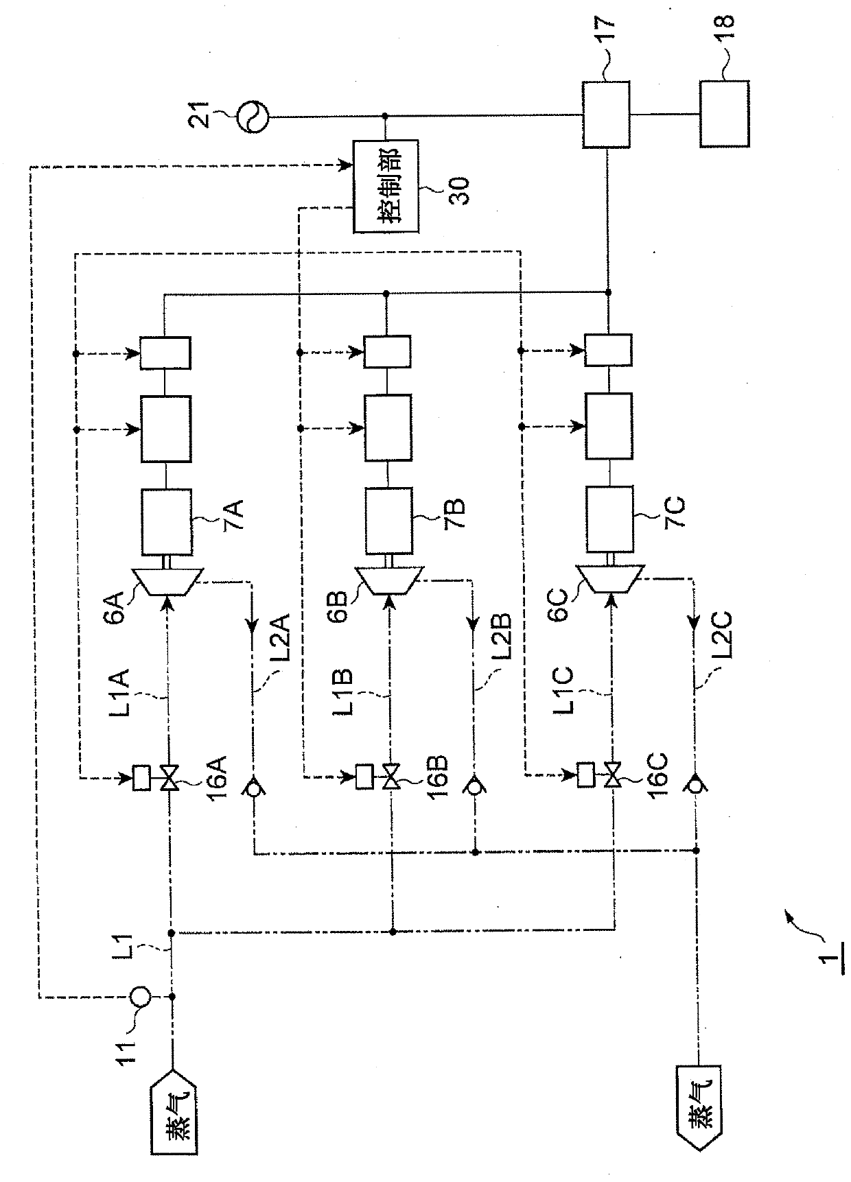
[0016] First, refer to figure 1 The steam power generation system 1 of this embodiment will be described. figure 1 In , the solid line represents the circuit. The dashed-two dotted line indicates the steam circuit. A dotted line connected to the control unit 30 represents a control loop. In this embodiment, steam is, for example, water vapor.

[0017] Such as figure 1 As shown, the steam power generation system 1 is a power generation system that performs power generation using high-temperature steam (for example, a pressure of 0.7 to 0.8 MPa and a temperature of about 170 to 180° C.) as a heat source. The steam power generation system 1 includes: a first scroll expander 6A, a second scroll expander 6B, and a t...


PUM


Abstract

A power generation system (1) includes a plurality of displacement type expanders (6A-6C), and a plurality of power generators (7A-7C) connected to each of the displacement type expanders(6A-6C), and generating power by expansion of steam at least at one of the displacement type expanders (6A-6C). The power generation system (1) includes a suppression means (16A-16C) that is capable of suppressing circulation of the steam for each of the displacement type expanders (6A-6C), and a control unit (30) that controls a load ratio for each of the displacement type expanders (6A-6C) by controlling the suppression means (16A-16C) based on information on the heat amount of the steam.

Description

technical field [0001] The invention relates to a power generation system and a power generation method. Background technique [0002] Conventionally, devices for generating electricity by expanding steam in an expander are known. For example, in the device described in Patent Document 1 (Japanese Patent Laid-Open No. 2012-202262 ), an evaporator, an expander, and a condenser form one power generation cycle, and a plurality of such power generation cycles are provided. In addition, a heating medium shutoff valve and a cooling medium shutoff valve are provided. In this device, the amount of power generation is detected, and the heating medium shutoff valve and the cooling medium shutoff valve are opened and closed based on the detected value of the power generation amount and the heating medium discharge temperature. [0003] As in the above-mentioned device, by setting multiple power generation cycles, it can cope with a large amount of heat. However, there has been no po...

Claims


Application Information

Patent Timeline
Patent Type & Authority Patents(China)
IPC IPC(8): F01K13/02F01K7/04F01C13/00F01C20/02F01C20/24
CPCF01K13/02F01K23/02
Inventor 藤冈完宇波厚和泉孝明
Owner ANEST IWATA CORP
Why Eureka
Try Eureka