A terminal cap thermal resistance connecting device

A Termination, Thermal Resistance Technology

Active Publication Date: 2019-01-04
THE GENERAL DESIGNING INST OF HUBEI SPACE TECH ACAD
View PDF7 Cites 0 Cited by
  • Summary
  • Abstract
  • Description
  • Claims
  • Application Information

AI Technical Summary

Problems solved by technology

At the same time, the high temperature on the end cap will also be transmitted to the cabin, and the harsh thermal environment will affect or damage the single machine and equipment in the cabin
Specifically, if the shell of the end cap is in direct contact with the metal shell of the cabin, its high temperature will be transmitted to the inside of the metal shell of the cabin through heat conduction, causing damage to the strength of the metal shell or damage to the single machine equipment in the cabin

Method used


Image

  • A terminal cap thermal resistance connecting device
  • A terminal cap thermal resistance connecting device
  • A terminal cap thermal resistance connecting device

Examples


Embodiment Construction

[0024] In order to make the object, technical solution and advantages of the present invention clearer, the present invention will be further described in detail below in conjunction with the accompanying drawings and embodiments. It should be understood that the specific embodiments described here are only used to explain the present invention, not to limit the present invention. In addition, the technical features involved in the various embodiments of the present invention described below can be combined with each other as long as they do not constitute a conflict with each other.

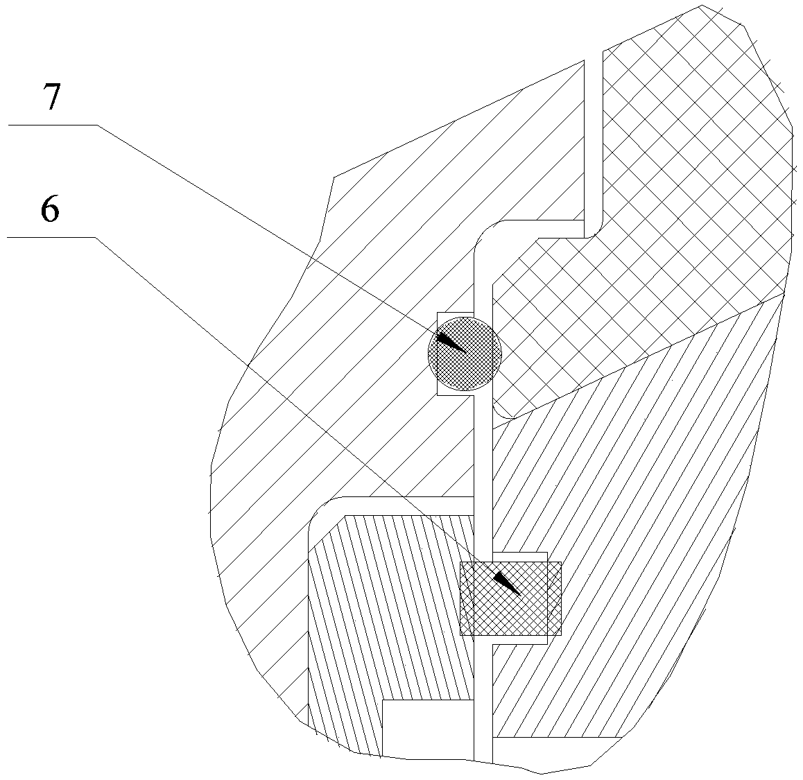
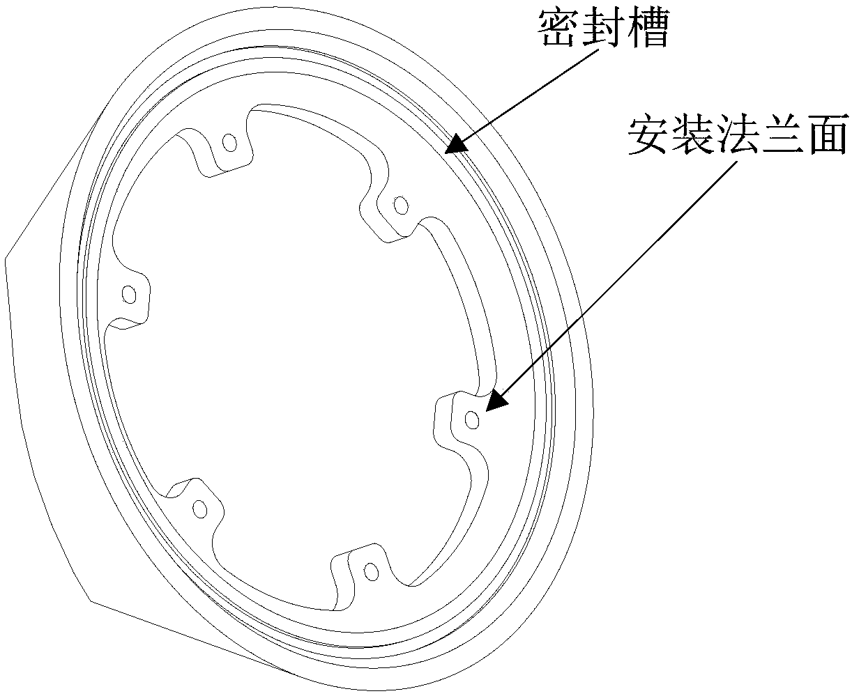
[0025] The terminal cap thermal resistance connection device disclosed in the present invention includes a terminal cap, a first adapter plate, a second adapter plate, a first sealing ring, a second sealing ring, and some necessary fasteners. The material of the end cap is a high temperature resistant structural material, typical materials such as tungsten infiltrated copper, which are mainly us...


PUM


Abstract

The invention discloses an end cap heat resistance connecting device, which comprises an end cap, a first transfer plate, a second transfer plate, a first sealing ring and a second sealing ring, wherein the end cap is in a conical tube shape; the large end of the end cap is provided with an installing flange surface and a sealing groove; the second sealing ring is arranged in the sealing groove of the end cap, and is tightly attached onto the end surface position of a heat insulation prevention layer covered on the surface layer of a front cabin metal casing at the same time; an end cap step surface is arranged on the end surface of the large end of the end cap; the end cap step surface is attached with a step surface arranged at the end surface position of the heat insulation prevention layer; the end cap is fixedly connected with the first transfer plate through the installing flange surface; the second transfer plate is fixed in the end surface position of the head part of the front cabin metal casing; the first transfer plate is fixedly connected with the second transfer plate; a sealing groove is formed in the end surface position of the head part of the front cabin metal casing; the first sealing ring is arranged in the sealing groove. The heat conduction on the cabin section can be effectively prevented; the temperature of the cabin body is enabled to be in the heat insulation prevention design requirement range.

Description

technical field [0001] The invention belongs to the field of heat-insulating structure design for aircraft cabins, and relates to an anti-heat insulation device used between an aircraft terminal cap and a cabin. Background technique [0002] During the supersonic flight of the aircraft, the aerodynamic heating of the end cap is serious, and it is necessary to carry out structural heat insulation design for this part. At the same time, the high temperature on the end cap will also be transmitted to the cabin, and the harsh thermal environment will affect or destroy the single machine and equipment in the cabin. Specifically, if the end cap shell is in direct contact with the metal shell of the cabin, its high temperature will be transmitted to the interior of the metal shell of the cabin through heat conduction, resulting in damage to the strength of the metal shell or damage to the stand-alone equipment in the cabin. [0003] Therefore, it is necessary to design a thermal r...

Claims


Application Information

Patent Timeline
Patent Type & Authority Patents(China)
IPC IPC(8): B64C1/40
CPCB64C1/40
Inventor 戴肇鹏王辉汪文龙范开春朱璇刘庆欧朝
Owner THE GENERAL DESIGNING INST OF HUBEI SPACE TECH ACAD
Why Eureka
Try Eureka