An automatic welding system for cylinder pipe joints and its application method

An automatic welding and cylindrical tube technology, applied in welding equipment, welding accessories, arc welding equipment and other directions, can solve the problems of difficult cleaning, large welding workload, high labor intensity, etc., to avoid close contact, manufacturing process Simple and effective in improving the working environment

Inactive Publication Date: 2018-06-19
CHANGSHA UNIVERSITY
View PDF7 Cites 0 Cited by
  • Summary
  • Abstract
  • Description
  • Claims
  • Application Information

AI Technical Summary

Problems solved by technology

Taking a certain steam boiler as an example, in its production process, the welding of the pipe joints in the upper drum is a major processing difficulty. The main difficulty is that the welding process is the assembly and welding of the boiler, and the workpiece cannot change its position freely; The space is small (the diameter of the smallest drum is only about 800mm), and it is difficult for people and equipment to move inside; the welding workload is large (there are more than 860 pipe joints in the upper drum); the welding quality requirements are high
All domestic manufacturers use manual arc welding, but there are many problems in the production process, such as: the working conditions of the workers are extremely poor, and the labor intensity is very high, which greatly affects the welding efficiency and welding quality; The slag, cleaning and grinding work is very heavy, and the grinding spatter and other garbage are easy to fall into the pipe, which is difficult to clean up and seriously affects the product quality of the boiler. At the same time, the entire welding height will present a symmetrical saddle shape. Therefore, in the automatic welding process of the tube body, it is an insurmountable difficulty to adjust the welding torch in time with the height of the weld seam

Method used


Image

  • An automatic welding system for cylinder pipe joints and its application method
  • An automatic welding system for cylinder pipe joints and its application method
  • An automatic welding system for cylinder pipe joints and its application method

Examples


Embodiment Construction

[0024] The present invention will be further described below in conjunction with the accompanying drawings and embodiments.

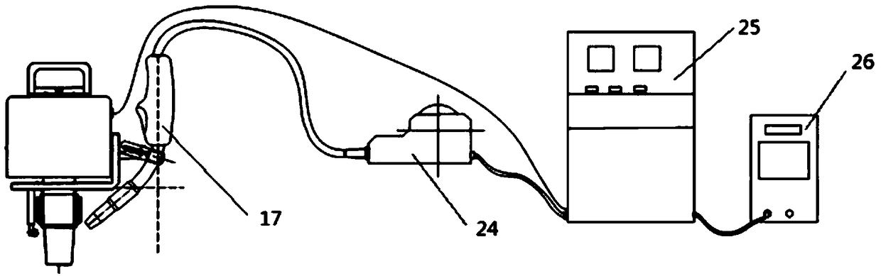
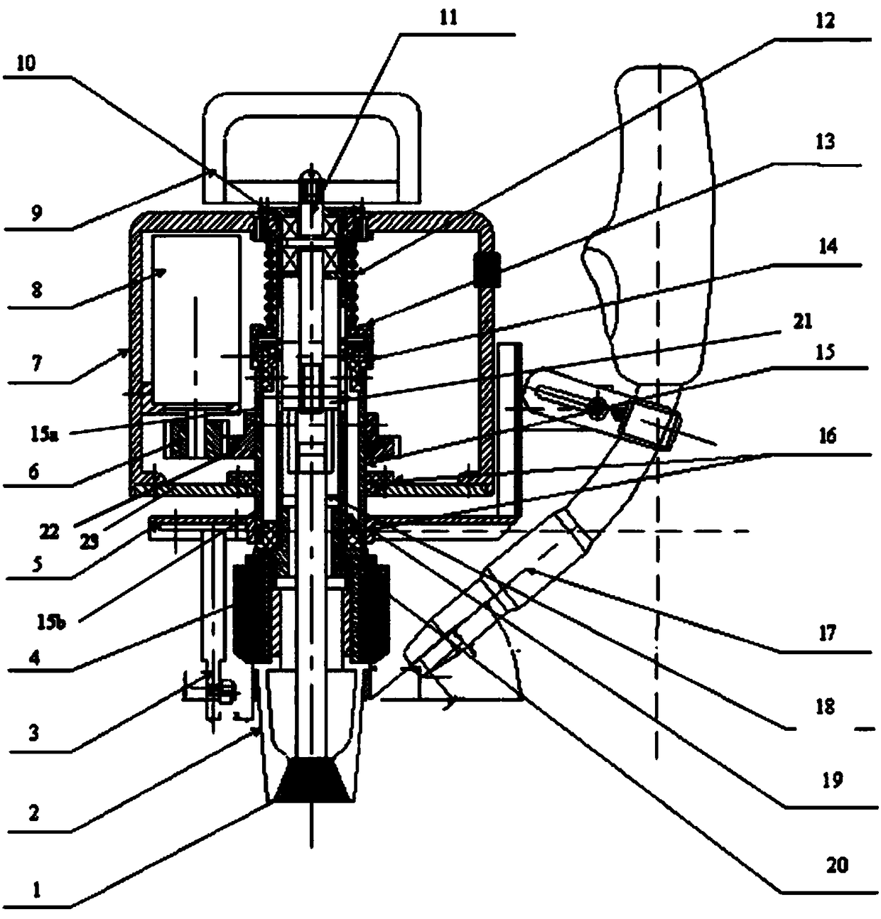
[0025] Such as figure 2 and 3 As shown, the cylinder pipe joint automatic welding system provided by the present invention includes an automatic welding machine, a wire feeder 24, a control mechanism 25, and an electric welding machine 26. The automatic welding machine includes a machine shell 7, and the top surface of the machine shell 7 is A first through hole is provided, and a base plate 23 is provided at the bottom end. A second through hole coaxial with the first through hole is provided on the base plate 23. A shaft sleeve 16 is arranged in the second through hole to support The upper end of the pipe 19 is sleeved in the first through hole, and is screwed and fixed to the top surface of the tool casing 7 through the flange on the pipe wall, and the lower end passes through the shaft sleeve 16 and extends outside the tool casing, and passes thro...


PUM

PropertyMeasurementUnit
diameteraaaaaaaaaa

Abstract

The invention discloses an automatic cylinder pipe joint welding system and a using method thereof. The automatic cylinder pipe joint welding system comprises an automatic welding machine, a wire feeder, a control mechanism and an electric welding machine, wherein a rotating cylinder is arranged on the automatic welding machine and is connected with a welding turntable; a compression spring is arranged at the upper end of the rotating cylinder; a height adjusting rod is arranged on one side of the rotating cylinder on the welding turntable; a welding gun is arranged on the opposite other side and is connected with the wire feeder; the wire feeder is connected with the electric welding machine via the control mechanism; a driving motor is electrically connected with the control mechanism. According to the system, the driving motor drives the welding gun and the height adjusting rod to rotate; the welding gun can change along the change of the welding line height; the height adjusting rod tightly presses the welding surface all the time in the welding process, thus ensuring that the distance between the welding gun and the welding surface remains unchanged all the time in the whole welding process. The automatic cylinder pipe joint welding system is especially suitable for welding cylinder pipe joints.

Description

technical field [0001] The invention relates to welding equipment, in particular to an automatic welding system for cylinder pipe joints and a method for using the same. Background technique [0002] Such as figure 1 As shown, in the production and manufacture of boilers and chemical equipment, it is often encountered that welding of saddle-shaped welds where two round pipes intersect is required. Because these components often work in harsh working environments such as high temperature and high pressure, the requirements for welding quality are very high. The work requires welding in the cylinder or pipe body. The closed working environment is very harsh, and the working area is very narrow, and the activities of the operators are limited inside. In the past, these weldings were all done manually by workers, which was labor-intensive and extremely low-efficiency. Taking a certain steam boiler as an example, in its production process, the welding of the pipe joints in the...

Claims


Application Information

Patent Timeline
Patent Type & Authority Patents(China)
IPC IPC(8): B23K9/12B23K9/32
CPCB23K9/12B23K9/32
Inventor 姚瑶
Owner CHANGSHA UNIVERSITY
Why Eureka
Try Eureka