
Optical cable line blocking information sensor

A sensor and optical cable technology, applied in the field of optical cable line blocking information sensors, can solve the problems of optical fiber communication transmission network failure, increase the blocking index of optical fiber communication transmission network, etc., and achieve the effect of easy popularization, low cost, and avoiding blocking

Inactive Publication Date: 2017-01-04
吴晓明
View PDF0 Cites 1 Cited by
  • Summary
  • Abstract
  • Description
  • Claims
  • Application Information

AI Technical Summary

Problems solved by technology

However, these methods have technical defects to varying degrees. The main problem is that the optical device needs to be connected in series between the optical transmission equipment and the optical cable line. Once the optical device itself fails, it will cause the failure of the optical fiber communication transmission network.
In addition, when installing the automatic monitoring system for optical cable lines, it is necessary to stop the operation to complete, which will undoubtedly increase the blocking index of the optical fiber communication transmission network

Method used


Image

  • Optical cable line blocking information sensor
  • Optical cable line blocking information sensor
  • Optical cable line blocking information sensor

Examples


Embodiment Construction

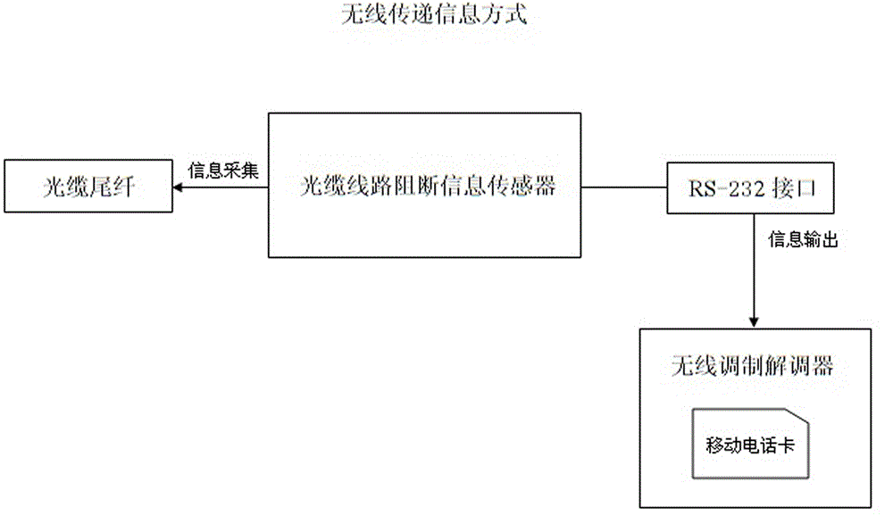
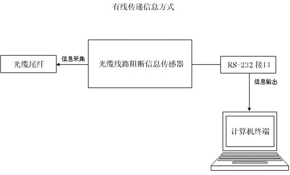
[0040] As shown in the figure, the present invention includes a grip-type optical signal collector and an integrated control circuit. The signal input end of the integrated control circuit is connected to the signal output end of the grip-type optical signal collector; the integrated control circuit includes NPN transistors Q1, PIC16F690 chip U1, MAX485 chip U3 and MAX232 chip U2, the base of Q1 is connected to the signal input terminal of the integrated control circuit through the resistor R8, the collector of Q1 is connected to the power supply VCC, and the emitter of Q1 is connected to one end of the resistor R9 and one end of the resistor R16 respectively The other end of R9 is connected to ground, and the other end of R16 is connected to pin 3 of U1.

[0041] Pin 1 of U1 is connected to power supply VCC, pin 4 of U1 is connected to one end of resistor R2, the other end of R2 is connected to one end of capacitor C1 and one end of resistor R1, the other end of C1 is grounded...


PUM


Abstract

The optical cable line blocking information sensor belongs to the electronic, communication and automation control technology and the computer science field, and particularly relates to an optical cable line blocking information sensor. The invention provides an optical cable line blocking information sensor which does not affect normal operation of an optical fiber communication transmission network and can effectively monitor the optical cable line blocking information. The optical cable line blocking information sensor comprises a grasping type optical signal collector and a comprehensive control circuit; the optical cable line blocking information sensor is characterized in that a signal input end of a comprehensive control circuit is connected to a signal output end of a grasping type optical signal collector; the comprehensive control circuit comprises an NPN triode Q1, a PIC16F690 chip U1, an MAX485 chip U3 and an MAX232 chip U2; a base electrode of a Q1 is connected to a signal input end of the comprehensive control circuit through a resistor R8; a collector electrode of the Q1 is connected to a power supply VCC; an emission electrode of the Q1 is connected to one end of an resistor R9 and one end of a resistor R 16; and the other end of the R9 is connected to the ground.

Description

technical field [0001] The invention belongs to the fields of electronics, communication and automatic control technology and computer science technology, and in particular relates to an optical cable line blocking information sensor. Background technique [0002] With the development of communication technology and optical fiber communication construction, the scale and coverage of optical fiber communication network are getting larger and larger, and it has become the main communication basis and means for people to transmit information daily, especially providing guarantee for the continuous expansion of computer Internet scale. [0003] The optical fiber communication transmission network is mainly composed of optical transmission equipment and optical cable lines. In the daily operation of the optical fiber communication transmission network, due to the long distance of the optical cable line and the wide coverage area, it is easy to be affected by many different factor...

Claims


Application Information

Patent Timeline
Patent Type & Authority Applications(China)
IPC IPC(8): H04B10/25H04B10/075
Inventor 吴晓明闫光卓郭金鹏
Owner 吴晓明
Learn More