
Construction method for reducing energy consumption of wound-rotor motor

A motor and winding technology, which is applied in the field of metallurgical energy and electricity, can solve the problems of increasing the cost of metallurgical enterprises, wasting electric energy, and high power consumption rate, and achieve the effects of ensuring safe and stable operation, solving large starting torque, and reliable circuit programs

Inactive Publication Date: 2017-01-04
武汉钢铁有限公司
View PDF4 Cites 0 Cited by
  • Summary
  • Abstract
  • Description
  • Claims
  • Application Information

AI Technical Summary

Problems solved by technology

[0002] Due to historical reasons, metallurgical energy enterprises have used a large number of wound motors, but the disadvantages of wound motors, such as the inability to adjust the speed, large starting current, and high energy consumption, have greatly increased the cost of metallurgical enterprises and threatened the safety of the terminal power grid.
[0003] Defects of wound wire motors: 1. The wound wire motor is a fixed-speed motor and cannot be adjusted. Regardless of the load, the output power of the drive source does not change, which wastes a lot of power and leads to high power consumption; 2. Winding The starting and running torque of the type motor is large, and it must be started manually with an external water resistance, which often affects production due to unsuccessful start; 3. The starting current of the winding type motor is 7 times the rated current, which has a large impact on the power grid. even cause an accident
[0004] Winding motors cannot be adjusted in speed, have large starting current and high energy consumption, which greatly increases the cost of metallurgical enterprises and threatens the safety of the terminal power grid.

Method used


Image

  • Construction method for reducing energy consumption of wound-rotor motor
  • Construction method for reducing energy consumption of wound-rotor motor
  • Construction method for reducing energy consumption of wound-rotor motor

Examples


Embodiment Construction

[0018] The present invention will be described in detail below in conjunction with the accompanying drawings and embodiments.

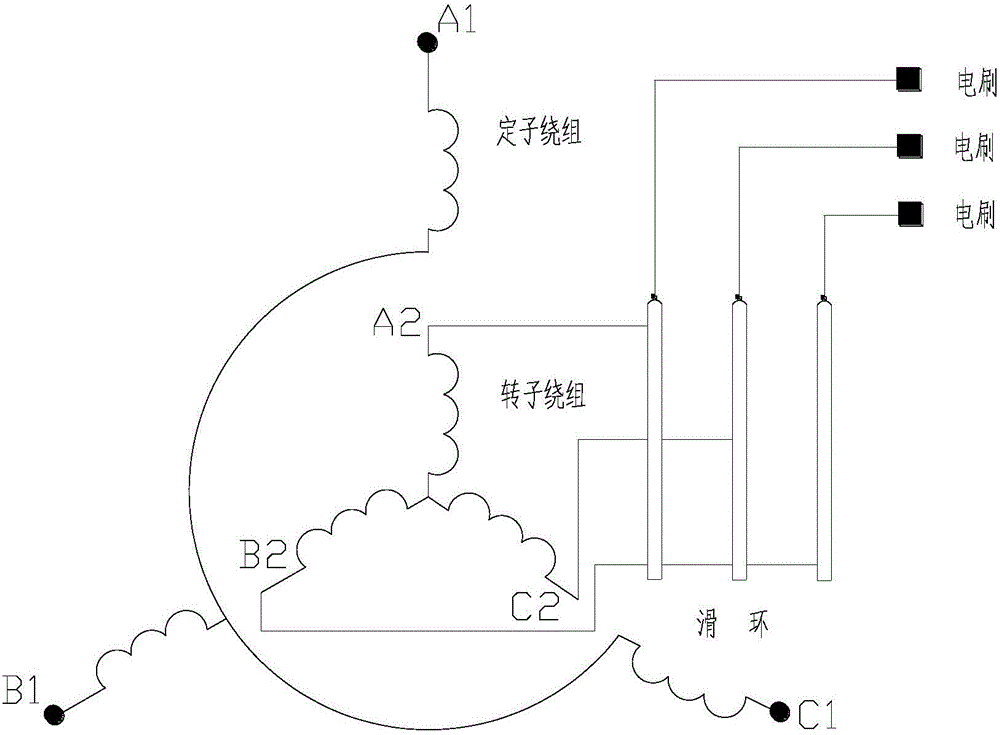
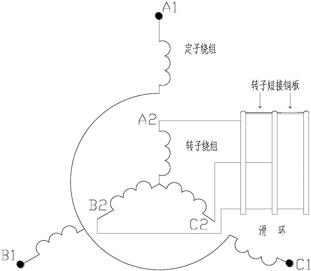
[0019] refer to Figure 1 ~ Figure 3 As shown, the modification method for reducing the energy consumption of a wound-type motor in an embodiment provided by the present invention includes the following steps: firstly short the three lead-out wires connecting the rotor of the wound-type motor with the collector ring through a shorting board Then install a set of control system 1 between the starting power supply and the modified winding motor; short-circuit the rotor through the short-circuit board to make the rotor form a squirrel-cage structure, and at the same time, use the frequency converter 4 to carry out the modified motor Start, not only start smoothly, but also save energy and electricity, solve the problem of large starting torque and high power consumption of wound motors, and avoid the huge impact of 7 times the starting current of wound m...


PUM


Abstract

The invention discloses a construction method for reducing energy consumption of a wound-rotor motor. The method comprises the following steps: first of all, short-connecting a rotor of the wound rotor motor with three lead-out wires connected with a collector ring through a short circuit board; and then additionally installing a control system between a starting power source and a constructed wound rotor motor. The application rate of the motor is improved, production safety can be guaranteed, the electricity consumption cost is greatly decreased, safe and stable operation of a power plant is ensured, the cost is not high, and manufacturing and maintenance are convenient.

Description

technical field [0001] The invention relates to the technical field of metallurgical energy and electricity, in particular to a transformation method for reducing energy consumption of a wound motor. Background technique [0002] Due to historical reasons, metallurgical energy enterprises have used a large number of wound motors, but the disadvantages of wound motors, such as the inability to adjust the speed, large starting current, and high energy consumption, have greatly increased the cost of metallurgical enterprises and threatened the safety of the terminal power grid. . [0003] Defects of wound wire motors: 1. The wound wire motor is a fixed-speed motor and cannot be adjusted. Regardless of the load, the output power of the drive source does not change, which wastes a lot of power and leads to high power consumption; 2. Winding The starting and running torque of the type motor is large, and it must be started manually with an external water resistance, which often a...

Claims


Application Information

Patent Timeline
Patent Type & Authority Applications(China)
IPC IPC(8): H02K15/00H02K11/30
CPCH02K15/0006H02K15/0012
Inventor 袁峰粟伟明杨勇王鹏程海付琳
Owner 武汉钢铁有限公司
Learn More