
Charging control circuit

A charging control and circuit technology, which is applied in the field of charging control circuits, can solve problems such as single charging function, inability to select charging methods, simple technology, etc.

Active Publication Date: 2017-01-04
CHNEGDU CHIFFO ELECTRONICS INSTR
View PDF2 Cites 0 Cited by
  • Summary
  • Abstract
  • Description
  • Claims
  • Application Information

AI Technical Summary

Problems solved by technology

The RF power reflectometer is usually used in different occasions and needs to be easy to carry. Therefore, it is equipped with a battery for easy use at any time. However, the existing charging control technology is simple, and it is impossible to select different charging methods according to the characteristics of the battery during charging. Single function

Method used


Image

  • Charging control circuit
  • Charging control circuit

Examples


Embodiment 1

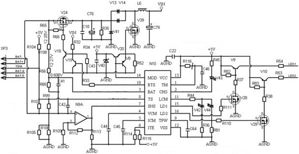
[0012]A charging control circuit, including a BQ2954 chip, the chip pin 1 is connected to a first capacitor C46, ​​a first resistor R116, the other end of the first capacitor C46 is grounded, and the other end of the first resistor is connected to a second capacitor C22 , +5V voltage interface, the other end of the second capacitor C22 is grounded; the chip pin 13 is grounded through the second capacitor C22; the chip pin 2 is connected to the second resistor R45 through the first light-emitting diode V43, so The other end of the second resistor R45 is connected to the +5V voltage interface, the chip pin 11 is connected to the third resistor R44, and the other end of the third resistor R44 is connected to the negative pole of the second light-emitting diode V42 and the negative pole of the third light-emitting diode V44. The anode of the second light-emitting diode V42 is connected to the fourth resistor R36, and the other end of the fourth resistor R36 is connected to the chip...


PUM


Abstract

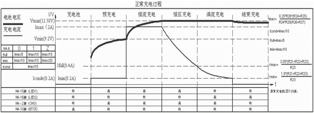
The invention discloses a charging control circuit, comprising a charging control chip and a peripheral circuit. The charging control circuit enables charging to switch between a constant current mode and a constant voltage mode according to a current battery state, and also enables the parameters such as charging voltage, charging current, charging time, charging power frequency and temperature protection, such that high efficiency and safety charging are achieved.

Description

technical field [0001] The invention relates to the field of battery charging, in particular to a charging control circuit. Background technique [0002] Power reflectometers are commonly used to measure the power of radio frequency (RF) or microwave frequency (MW) signals. A typical power reflectometer uses a power detector or transducer to convert RF or MW power into an easily measurable electrical quantity. Power reflectometers also have applications in many types of RF and MW systems. The RF power reflectometer is usually used in different occasions and needs to be easy to carry. Therefore, it is equipped with a battery for easy use at any time. However, the existing charging control technology is simple, and it is impossible to select different charging methods according to the characteristics of the battery during charging. Single function. Contents of the invention [0003] The present invention overcomes the above-mentioned shortcomings of the prior art and prov...

Claims


Application Information

Patent Timeline
Patent Type & Authority Applications(China)
IPC IPC(8): H02J7/00
CPCH02J7/007H02J7/00718H02J7/0091Y02E60/10
Inventor 李杰蒋承武
Owner CHNEGDU CHIFFO ELECTRONICS INSTR
Learn More