
De-mux liquid crystal display (LCD) equipment and driving method thereof

A liquid crystal display and equipment technology, applied in the field of De-mux liquid crystal display equipment and its drive, can solve the problems of fast switching frequency of switching tubes, high power consumption, and large power consumption of display equipment, and achieve the effect of reducing power consumption

Active Publication Date: 2017-01-04
WUHAN CHINA STAR OPTOELECTRONICS TECH CO LTD
View PDF10 Cites 44 Cited by
  • Summary
  • Abstract
  • Description
  • Claims
  • Application Information

AI Technical Summary

Problems solved by technology

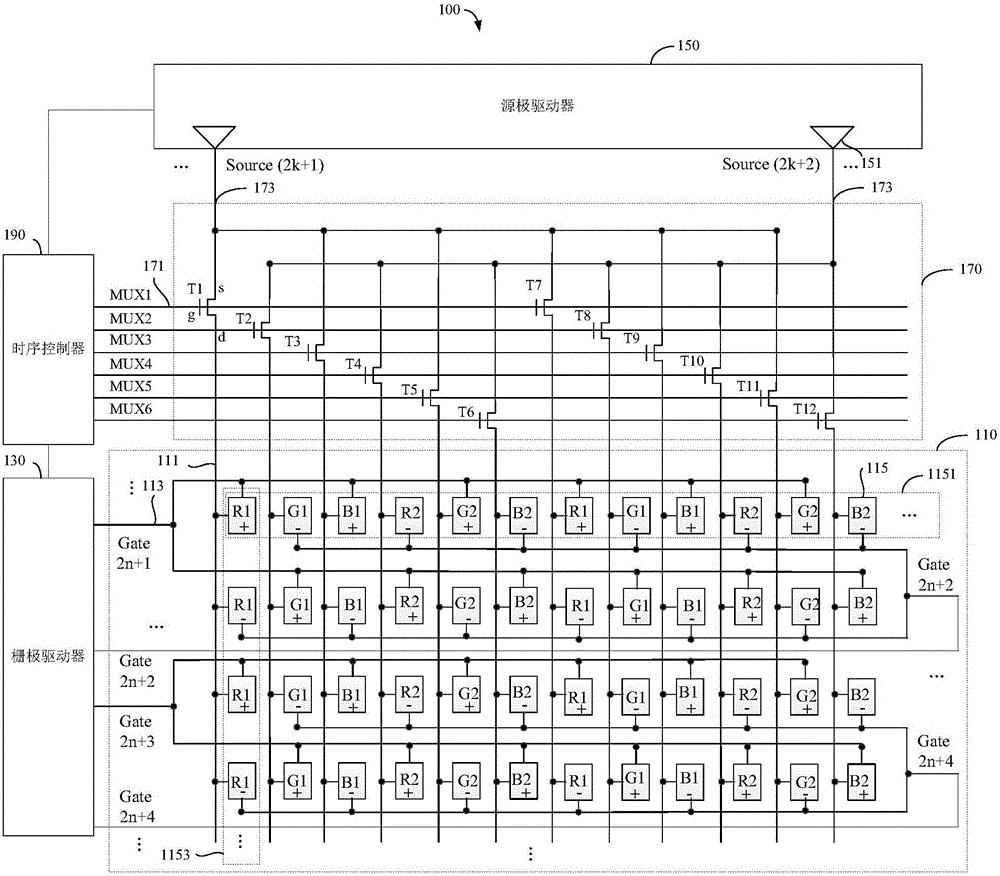
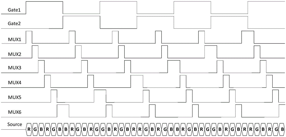
The existing 1to 6De-mux drive architecture is most commonly used in LCD devices with column inversion (Column inversion) drive mode. This architecture consumes a lot of power in the dot inversion (Dot inversion) drive mode, and each row During the scanning period, each gate signal must be level-shifted once. If the resolution line number of the De-mux liquid crystal display device is N, the switch tube corresponding to each gate signal needs to switch N in one frame period. times, to meet the requirements of the normal operation of the entire LCD, which will undoubtedly lead to too fast switching frequency of the switching tube, resulting in excessive power consumption of the entire De-mux LCD device

Method used


Image

  • De-mux liquid crystal display (LCD) equipment and driving method thereof
  • De-mux liquid crystal display (LCD) equipment and driving method thereof
  • De-mux liquid crystal display (LCD) equipment and driving method thereof

Examples


Embodiment Construction

[0033] The following will clearly and completely describe the technical solutions in the embodiments of the present invention with reference to the accompanying drawings in the embodiments of the present invention. Obviously, the described embodiments are only some of the embodiments of the present invention, not all of them. Based on the embodiments of the present invention, all other embodiments obtained by persons of ordinary skill in the art without making creative efforts belong to the protection scope of the present invention.

[0034]For ease of description, spatially relative terms such as "under", "beneath", "below", "above", "on" and other spatially relative terms may be used herein to describe an element as shown in the drawings Or the relationship of a feature to another element or feature(s). It will be understood that when an element or layer is referred to as being "on," "connected to," or "coupled to" another element or layer, it can be directly on, directly on...


PUM


Abstract

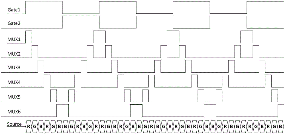
The embodiment of the invention provides a driving method of De-mux liquid crystal display (LCD) equipment. The driving method comprises the following steps: controlling the sub-pixels in the odd bits in a corresponding sub-pixel row and the sub-pixels in the even bits in the next adjacent sub-pixel row by an odd-numbered gate line in a display panel; controlling the sub-pixels in the odd bits in a sub-pixel row corresponding to an even-numbered gate line and the sub-pixels in the even bits in a sub-pixel row corresponding to the odd-numbered gate line by the next even-numbered gate line adjacent to the odd-numbered gate line in the display panel; in each row scanning cycle, controlling time-sharing on of switch tubes connected with L-numbered gate control terminals in a multiplex circuit in sequence by L-numbered paths of gating signals, wherein the last active level of the gating signals in each row scanning cycle is connected with the first active level of the gating signals in the adjacent scanning cycle. Besides, the embodiment of the invention also provides the De-mux LCD equipment. The LCD equipment has lower power consumption.

Description

technical field [0001] The invention relates to the field of liquid crystal display, in particular to a De-mux liquid crystal display device and a driving method thereof. Background technique [0002] In the traditional liquid crystal display device driving architecture, a data line (Dataline) and a scanning line (Gate line) are respectively connected to a pixel electrode. This approach can well control the opening and closing of the gate on each Gate line. Input of data on each Data line. However, with the increase in the resolution and resolution of liquid crystal display devices, the number of Data lines and Gate lines will also increase, thus affecting the penetration rate and display effect. In recent years, with the development of low temperature polysilicon (Low Temperature Poly-silicon, LTPS) technology, the charging capability of thin film transistors (Thin Film Transistor, TFT) has been improved, and multiplexed driving architectures have been widely used, such as...

Claims


Application Information

Patent Timeline
IPC IPC(8): G02F1/1345G02F1/1362G09G3/36
Inventor 方泽邢振周王科
Owner WUHAN CHINA STAR OPTOELECTRONICS TECH CO LTD
Learn More