
Scanning and range finding sensor

A scanning ranging and sensor technology, applied in the direction of measuring distance, instruments, measuring devices, etc., can solve the problems of reduced service life, increased device size and weight, and high cost

Active Publication Date: 2017-01-04
SHANGHAI SLAMTEC
View PDF5 Cites 6 Cited by
  • Summary
  • Abstract
  • Description
  • Claims
  • Application Information

AI Technical Summary

Problems solved by technology

Due to the large size of the TOF ranging module used, and the multiple sets of optical lenses contained in it need to be precisely fixed during work, it has brought great challenges to the design and production of this type of scanning ranging device, and has led to this type of scanning The cost of the distance measuring device is higher
At the same time, complex optics also increase the size and weight of the device
These factors greatly limit the application of this type of scanning ranging device in the field of cost- and volume-sensitive consumer goods
In addition, with the development of robot technology, the requirements for the size of the distance measuring device are getting higher and higher. The size of the traditional distance measuring device is still too large, and when the slip ring is used for power supply and signal transmission, the service life will be greatly reduced. reduce
Furthermore, when the scanning motor drives the distance measuring unit of the rotating part to rotate through the pulley or gear, the pulley or gear often wears out after long-term operation, which affects the normal operation of the distance measuring device

Method used


Image

  • Scanning and range finding sensor
  • Scanning and range finding sensor
  • Scanning and range finding sensor

Examples


Embodiment Construction

[0030] In order to make the technical content disclosed in this application more detailed and complete, reference may be made to the drawings and the following various specific embodiments of the present invention, and the same symbols in the drawings represent the same or similar components. However, those skilled in the art should understand that the examples provided below are not intended to limit the scope of the present invention. In addition, the drawings are only for schematic illustration and are not drawn according to their original scale.

[0031] The specific implementation manners of various aspects of the present invention will be further described in detail below with reference to the accompanying drawings.

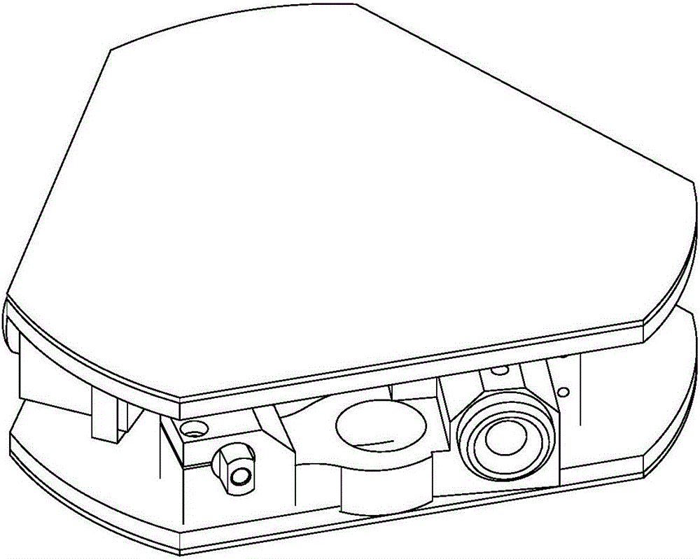
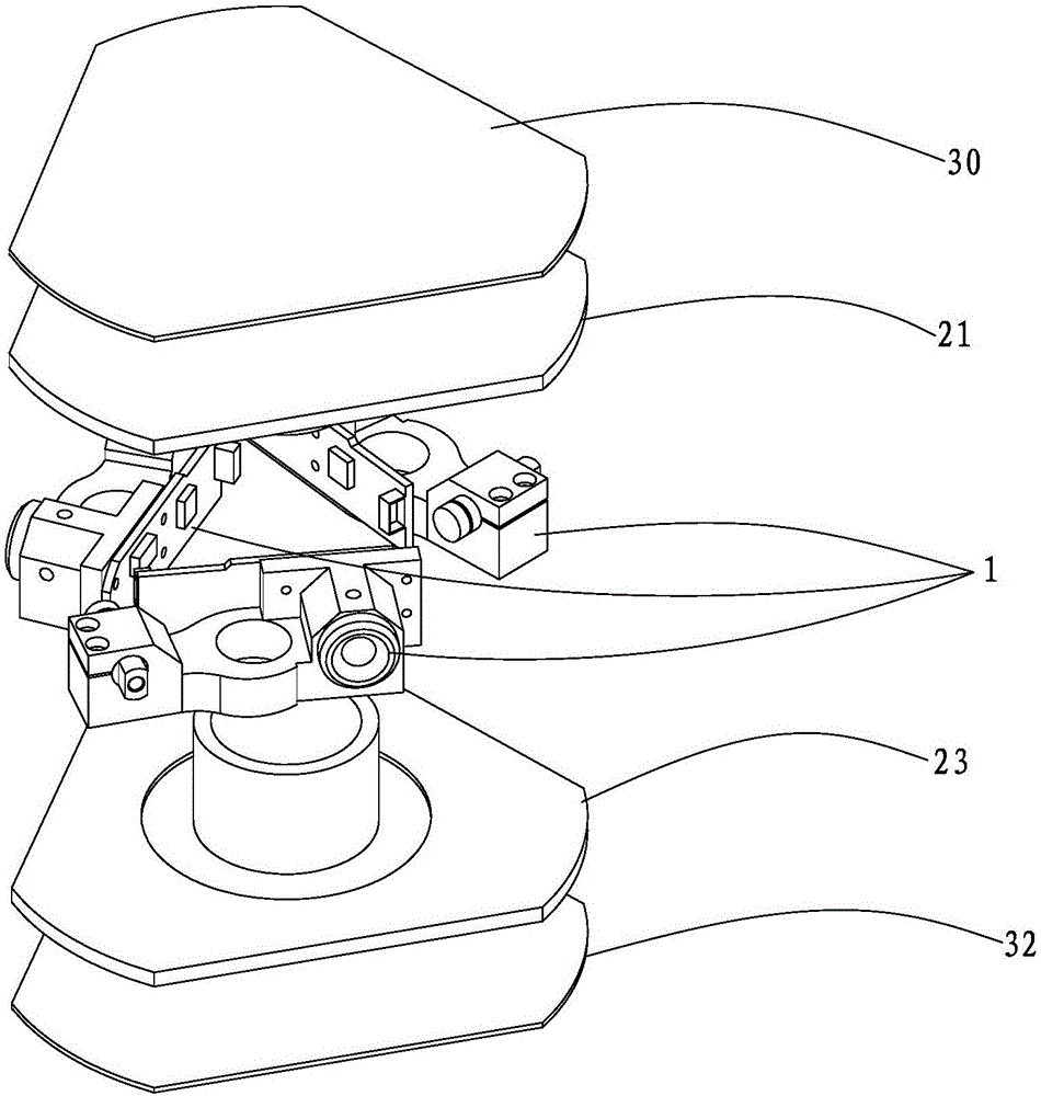
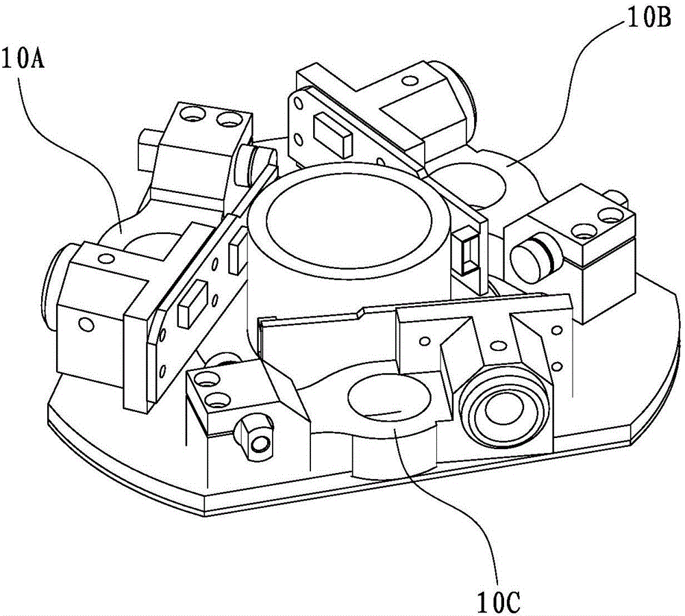
[0032] figure 1 It shows a stereoscopic view of a scanning ranging sensor based on a plurality of ranging units according to an embodiment of the present invention. figure 2 show figure 1 An exploded schematic of the scanning ranging sensor. Figure 3A...


PUM


Abstract

The invention provides a scanning and range finding sensor. The sensor includes a spinning part and a fixed part. The spinning part is arranged on the outside and spins around the fixed part. The spinning part includes at least three range finding units. Each range finding unit includes a light emitting module, a light receiving module, an installation structure member and a signal processing circuit. The fixed part includes a pedestal and a signal receiving unit. A wireless power supply module includes an emitting coil and a receiving coil which are respectively installed on the fixed part and the spinning part and transmit electricity through magnetic coupling between the coils. Compared with prior art, according to the invention, the sensor combines multiple range finding methods, such as triangle range finding, phase range finding, and pulse range finding, etc, and fully make use of best range finding range of range finding units of different types, such that the sensor is able to implement range finding with high precision of short range, middle range and distant range. Also, according to the invention, the sensor replaces a slip ring of prior art with the wireless power supply module for connection, which can increase the frequency of range finding and prolongs service life.

Description

technical field [0001] The invention relates to a laser ranging technology, in particular to a scanning ranging sensor based on a plurality of ranging units. Background technique [0002] Optical scanning ranging is a new technology that uses collimated beams to perform non-contact scanning and ranging of target objects. By rotating the collimated beams (such as lasers) used for ranging within a certain Objects in the environment are scanned and ranging, and the contour information of the environment is extracted. Compared with ultrasonic, image detection and other methods, the use of optical scanning ranging technology can achieve very high ranging accuracy and fast ranging speed. Therefore, it has very high application value in industrial and civil fields, and is currently widely used in fields such as robot autonomous mapping and navigation positioning (SLAM), 3D scene reconstruction, and security detection. [0003] In the prior art, the early scanning distance measuri...

Claims


Application Information

Patent Timeline
IPC IPC(8): G01S17/48G01S17/08
CPCG01S17/08G01S17/48
Inventor 刘健徐磁汪迎春张扬陈士凯李宇翔林凌刘义春黄珏珅
Owner SHANGHAI SLAMTEC
Learn More