
Wireless communication system for managing an underground facility

A technology for wireless communication systems and underground facilities, which is applied in the field of wireless communication systems and can solve the problem that sensing signals cannot be sent to the ground.

Inactive Publication Date: 2010-09-08
KOREA ELECTRONICS TECH INST
View PDF4 Cites 3 Cited by
  • Summary
  • Abstract
  • Description
  • Claims
  • Application Information

AI Technical Summary

Problems solved by technology

However, the sensing signals detected by the sensors cannot be sent to the ground using traditional communication methods utilizing RFID / USN technology

Method used


Image

  • Wireless communication system for managing an underground facility
  • Wireless communication system for managing an underground facility
  • Wireless communication system for managing an underground facility

Examples


Embodiment Construction

[0031] The above-mentioned features and additional features of the present invention will become more apparent from the preferred embodiments described in detail with reference to the accompanying drawings. In order to enable those skilled in the art to more fully understand and reproduce the present invention, preferred embodiments will be described in detail below.

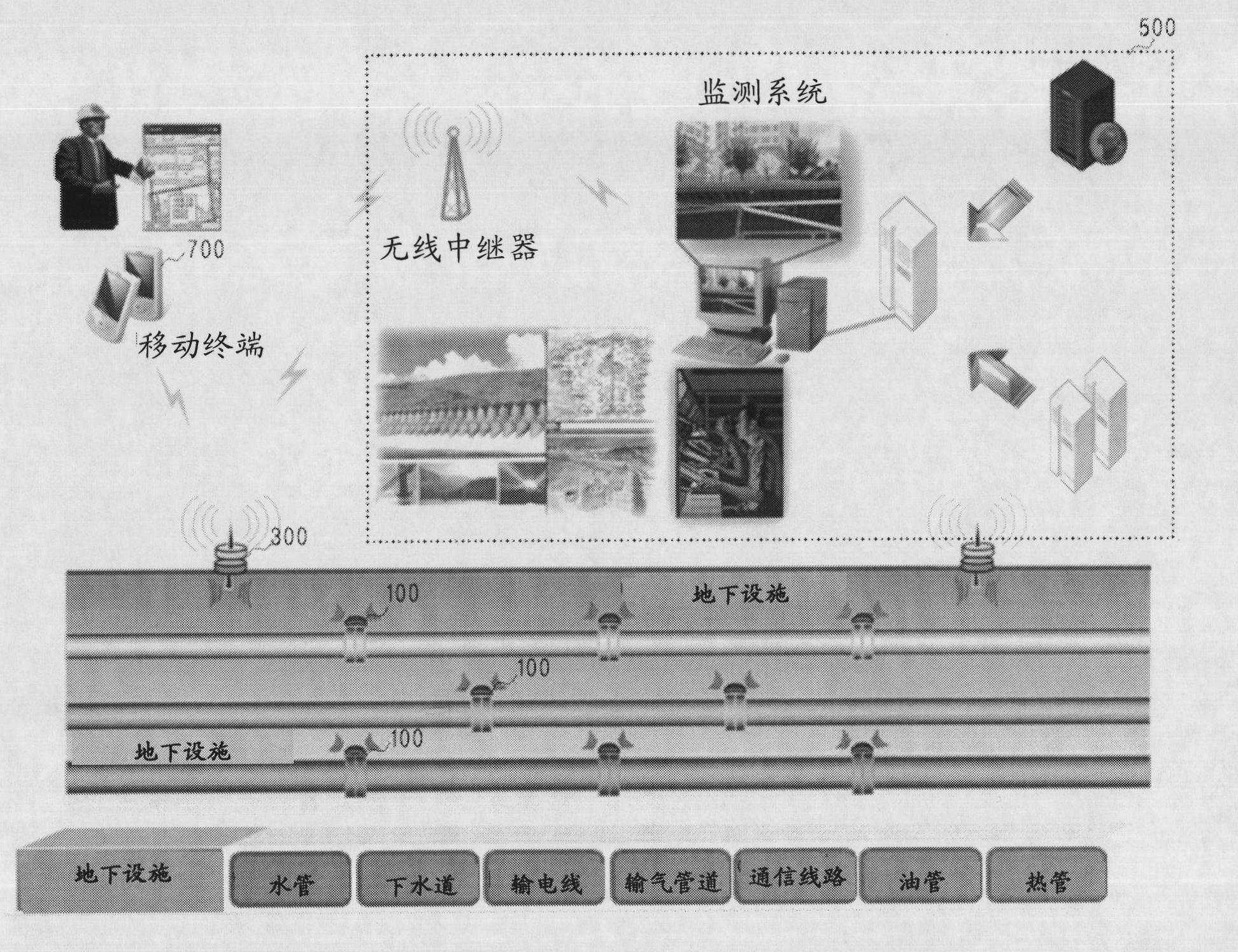
[0032] figure 2 is a schematic diagram showing a wireless communication system for managing underground facilities according to a preferred exemplary embodiment of the present invention.

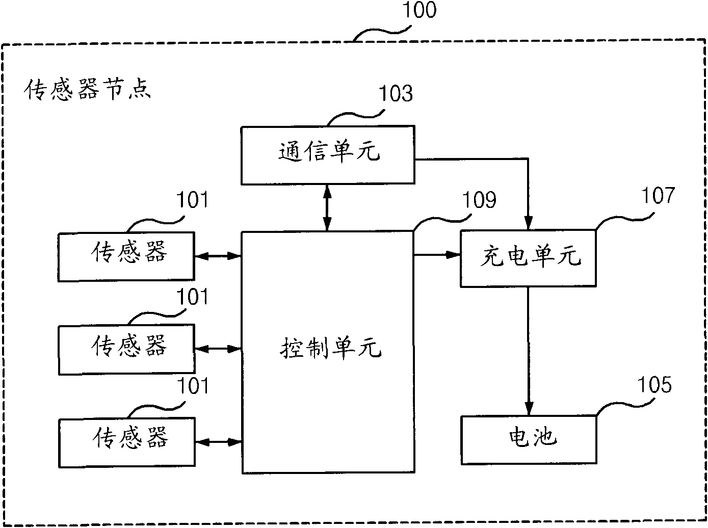
[0033] A wireless communication system for managing an underground facility according to an exemplary embodiment of the present invention includes: a plurality of sensor nodes 100 attached to the underground facility, which pass The magnetic field communication sends the sensing signal; the information collection device 300 sends the driving signal to the sensor node 100, collects the sensing signal sent from the sensor node...


PUM


Abstract

A wireless communication system for managing an underground facility includes: at least one sensor node attached to the underground facility configured to transmit a sensing signal via magnetic field communication after detecting the status information of the underground facility in accordance with a driving signal, the driving signal comprising a wake-up signal; and an information collection device configured to: transmit the driving signal to the sensor node; collect the sensing signal transmitted from the sensor node; and transmit the collected information to a monitoring system via short-range wireless communication.

Description

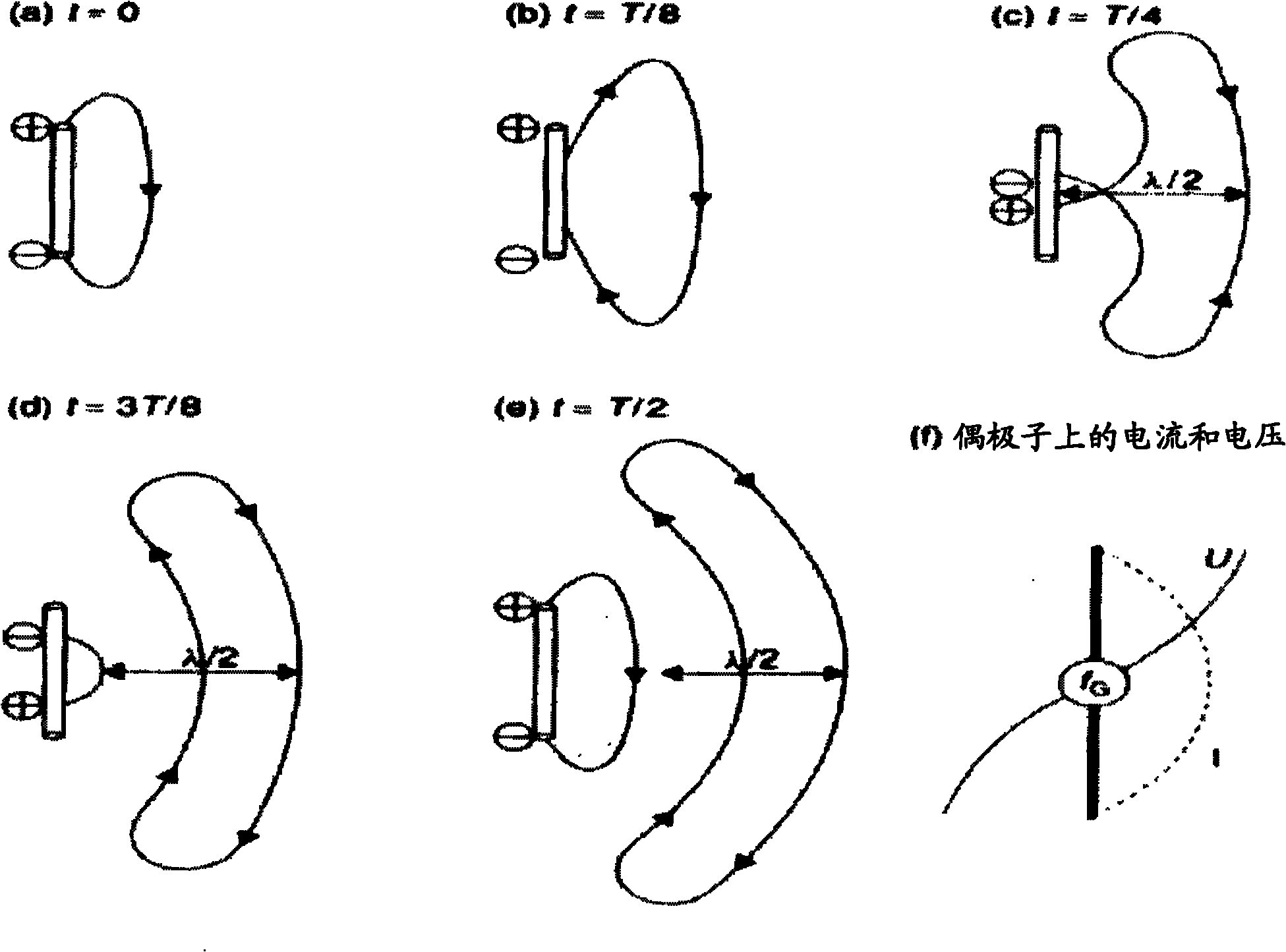
technical field [0001] The present invention relates to a wireless communication system for managing underground facilities, and more particularly, to a wireless communication system for managing underground facilities capable of providing their accurately measured status information for wireless communication in harsh underground environments. Background technique [0002] Magnetic field communication is a wireless communication system that utilizes a magnetic field within an area defined by a distance λ / 2π from the antenna at which the electromagnetic field is separated from the antenna and propagates into free space in the form of electromagnetic waves. Magnetic field communications work reliably in harsh environments containing metal, water, soil, or collapsed building debris. [0003] figure 1 is a schematic diagram showing generation of a magnetic field region for magnetic field communication. When an AC voltage is applied between the feed points of a dipole antenna,...

Claims


Application Information

Patent Timeline
IPC IPC(8): H04W84/18G01R33/02G01S5/02
CPCH04Q2209/84H04Q2209/43H04Q2209/50H04Q9/00H04Q2209/60H04Q2209/883H04W84/18H04W88/18H04B5/73G01S19/13
Inventor 元允载林承玉金善熙赵镇雄
Owner KOREA ELECTRONICS TECH INST
Learn More